Saia-Burgess Controls AG
Manual I/O-modules for PCD1 │ PCD2 series │ Document 27-600 – Release ENG09 │ 2019-05-01
A-6
Appendix
Installation direction and relays contact protection
A
A.6.2 Installation direction for switching low voltages
Scope: PCD2.A200 and PCD3.A200
PCD2.A210 and PCD3.A210
PCD2.A220 and PCD3.A220
■ For safety reasons, extra low voltage (up to 50 V) and low voltage (50 … 250 V)
must not be connected to the same module.
■ Neitherdierentphasesmaybeconnectedtothesamemodule.
If a Saia PCD
®
system module is connected to a higher voltage (50 … 250 V) ap-
proved components for this voltage have to be used for all elements which are
galvanically connected to the system.
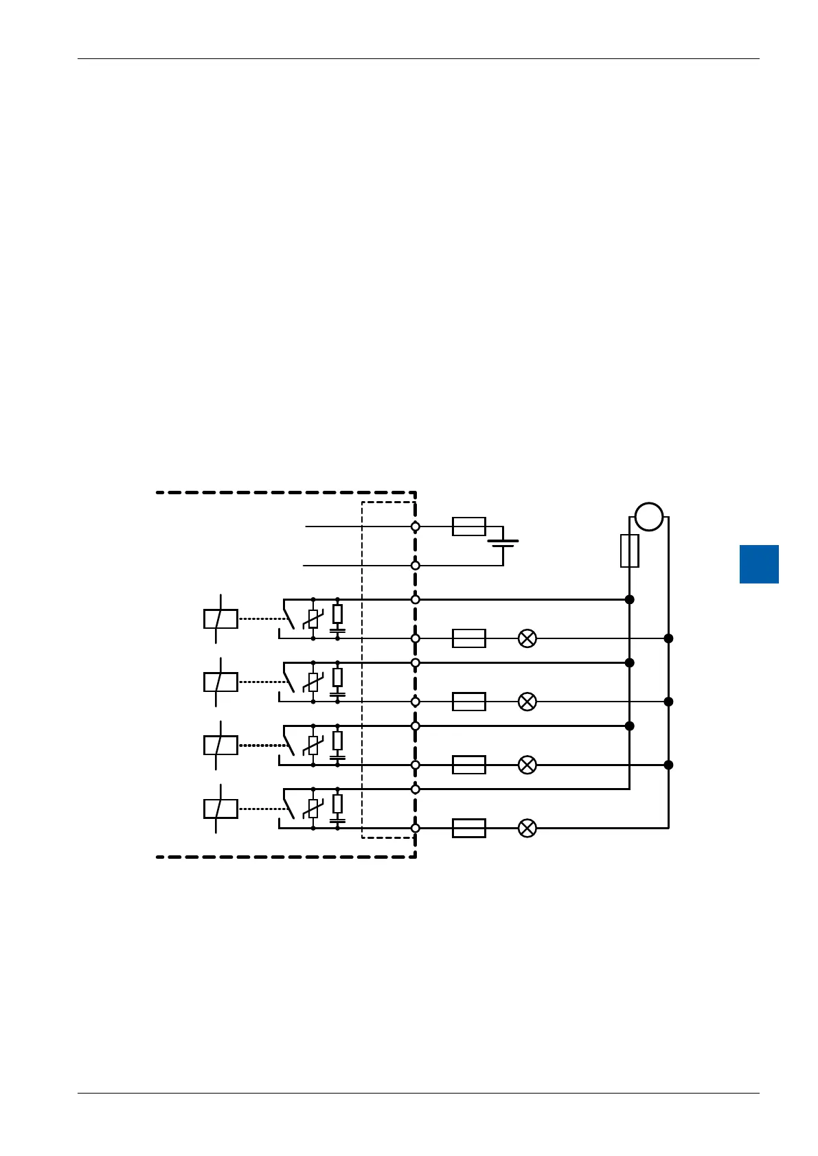
Using higher voltage (50 … 250 V), all connections to the relay contacts are to be
connected on the same circuit. That means at one point in such a way that they
are all protected against one AC-phase by only one fuse. Each load circuit may be
protected individually by a fuse of max. 2 A.
Connection example PCD2.A200 and PCD3.A200:
Terminal block
NO - O3
NO - O2
NO - O1
NO - O0
+24 VDC
GND
Supply voltage
of the relays
Load 1
Load 0
Load 3
Load 2
Si 3
Si 2
Si 1
Si 0
Si
0-3
max. 10 A
Si
max. 2 A
max. 2 A
max. 2 A
max. 2 A
C - O3
C - O2
C - O1
C - O0
+24 VDC
+230 VAC
~