Saia-Burgess Controls AG
Manual I/O-modules for PCD1 │ PCD2 series │ Document 27-600 – Release ENG09 │ 2019-05-01
6-83
I/O modules PCD3
PCD3.W6x0
6
6.10.2 PCD3.W6x0, analogue outputs, 4 channels, 12 bit resolution
Application
High-speed output module for general use with 4 channels, each with 12 bit reso-
lution.Dierentvariantsforvoltage0…10V,–10…+10Vandcurrent0…20mAare
available.
Module overview
PCD3.W600: Unipolar voltage outputs 0…10 V
PCD3.W610: Bipolar voltage outputs –10 V…+10 V,
switchable to unipolar voltage 0…10 V / current 0…20 mA
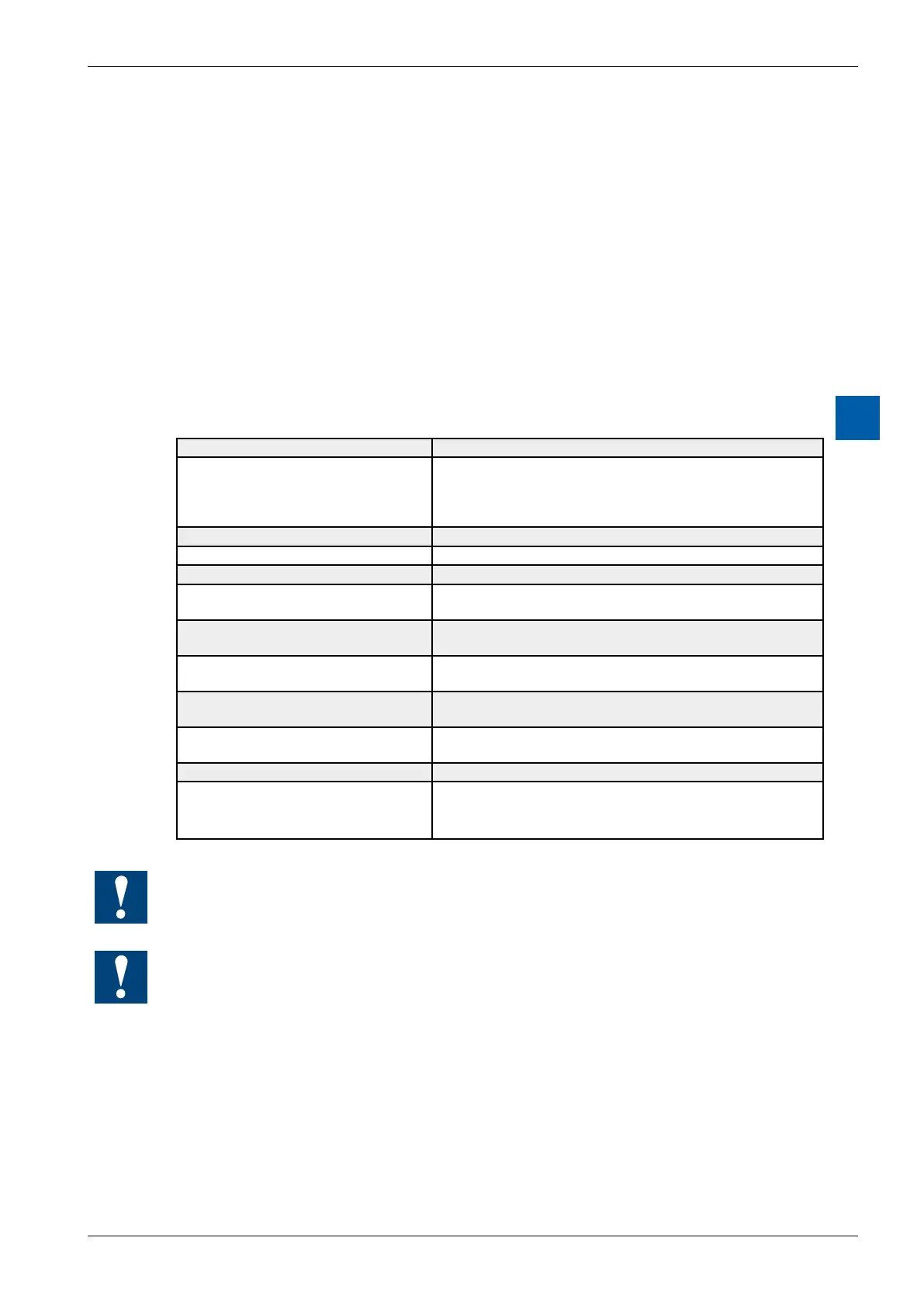
Technical data Resolution
Number of output channels: 4, short circuit protected
Signal range: W600: 0…+10 V 2.442 mV
W610: –10 V…+10 V 4.884 mV selectable
0…+10 V 2.442.mV with
0…20mA 4.884μA
}
jumper
Galvanic separation: no
Resolution (digital representation): 12 bits (0…4095)
Conversion time D/A: typ.10μs
Load impedance Voltage: >3kΩ
Current: <500Ω
Accuracy at 25°C (of output value) Voltage: ± 0.5 %
Current: ±0.8%*)
Temperature error: Voltage: ± 0.1 % (over temperature range
Current: ± 0.2 % 0…+55 °C)
Internal current consumption:
(from +5 V bus)
W600: max. 4 mA
W610: max. 110 mA
Internal current consumption:
(from V+ bus)
W600: max. 20 mA
W610: 0 mA
External current consumption: max. 100 mA (type PCD3.W610 only, for current outputs)
Terminals:
Plug-in 10-pole spring terminal block (4 405 4954 0) or
pluggable 10-pole screw terminal block (4 405 4955 0),
both for wires up to 2.5 mm²
*)Noteoncurrentoutputs:
Since for some applications it is important to be able to reach the outside limit values of the
range (0 mA, 20 mA), current outputs have been laid out according to the following charac-
teristic line:
During start-up, a voltage of 5 V is sent to all outputs of the W600 module. The start-up
phase lasts 40 ms, then 0 V is sent to the outputs.