Saia-Burgess Controls AG
Manual I/O-modules for PCD1 │ PCD2 series │ Document 27-600 – Release ENG09 │ 2019-05-01
9-10
PCD2.G200
Preparing the PLC system
9
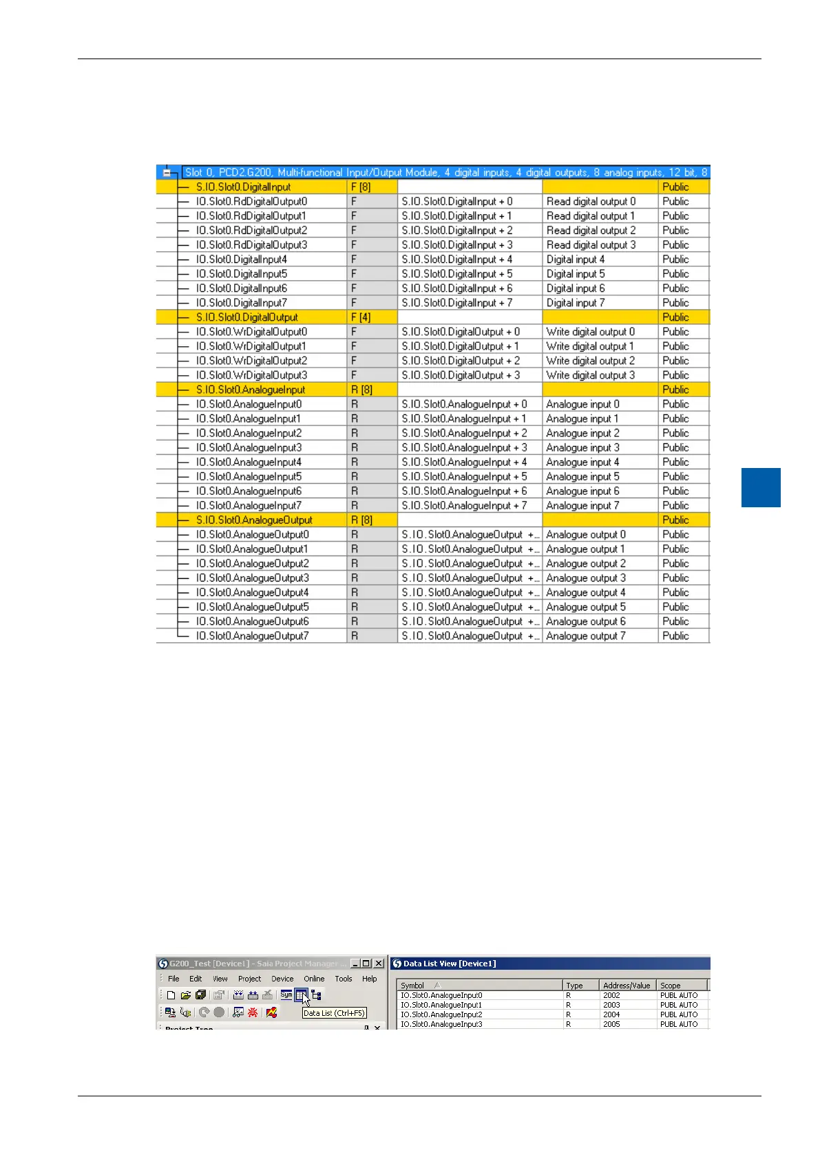
9.3.2.2 Media mapping
With media mapping, each PCD2.G200 module uses the following registers:
Figure 13: PG5, media mapping
In the user program the analogue I/O’s are accessed with the symbols:
Example: set Analog Output2 to 5V :
LD IO.Slot0.AnalogueOutput2
5000 ; range selected= 10000mV
The CPU reads the inputs at before executing the COB and updates the outputs
after executing the COB.
For „mixed“ I/O Modules as the PCD2.G200 the digital outputs have also a input
symbol IO.Slot0.RdDigitalOutput0…3 , but these are not used in this case.
To write the outputs only the symbols IO.Slot0.WrDigitalOutput0…3 are used.
TheeectiveaddressescanbeseenintheDataListView:
Figure14:eectiveaddresses