Saia-Burgess Controls AG
Manual I/O-modules for PCD1 │ PCD2 series │ Document 27-600 – Release ENG09 │ 2019-05-01
6-20
I/O modules PCD3
PCD3.E500
6
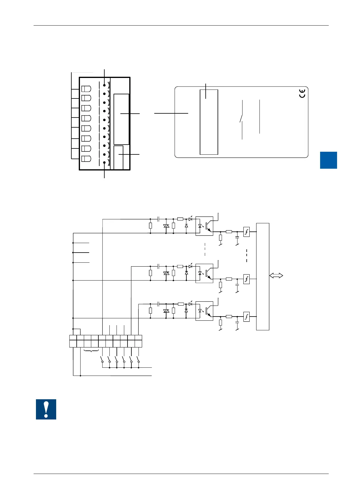
LEDs and connection terminals
En
PCD3.E500
6 Inputs
115-230 VAC
0
1
2
3
4
5
6
7
8
9
E0
E1
E2
E3
E4
E5
COM
COM
LED 0...7
E
5
0
0
0
1
2
3
4
5
6
7
COM
115-230 VAC
nc
nc
50/60 Hz
P
N
Terminal 9
Terminal
Description
Label
Address
Label
Input circuits and terminal designation
empty
Phase 115 - 230V 50/60 Hz *)
Neutral lead *)
*) Could be changed, if allowed
COM
COM
Switch closed
(positive at input) : Input state "H" = LED on
Switch open : Input state "L" = LED off
Watchdog:Thismodulecanbeusedonallbaseaddresses;thereisnointeractionwiththe
watchdog on the CPUs.
For details, please refer to the section A4 “Hardware Watchdog”, which describes the correct
use of the watchdog in conjunction with PCD components.