Saia-Burgess Controls AG
Manual I/O-modules for PCD1 │ PCD2 series │ Document 27-600 – Release ENG09 │ 2019-05-01
6-46
I/O modules PCD3
PCD3.A810
6
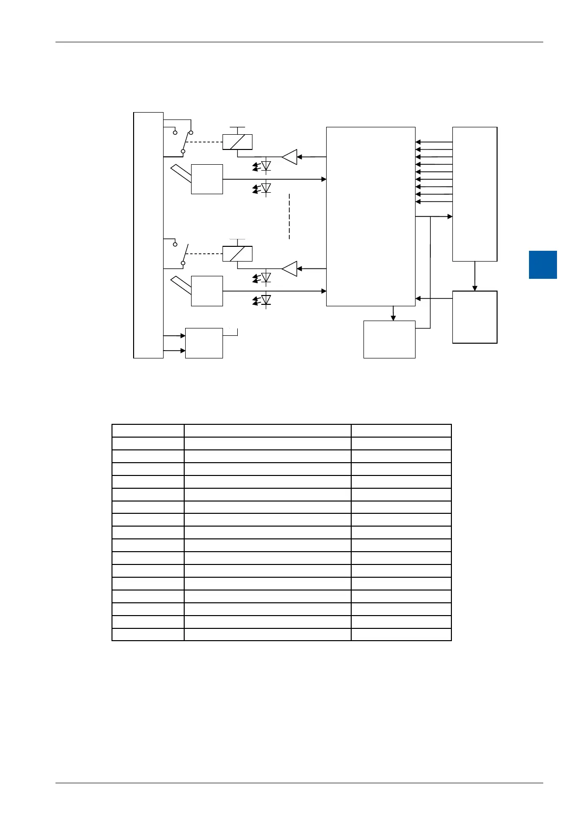
Block diagram
A0 no
A0 co
A3 no
A3 co
+Uext
GND
PCD3
I/O Bus
CPLD
Supply
3V3
Addressing
The PCD3.A810 occupies 16 addresses, of which 8 are used:
Address + BA
Data read (inputs) Data write (outputs)
0
Switch state: Output 0 Output 0
1
Switch state: Output 1 Output 1
2
Switch state: Output 2 Output 2
3
Switch state: Output 3 Output 3
4
5
6
7
8
Switch:Output0(0=auto;1=man)
9
Switch:Output1(0=auto;1=man)
10
Switch:Output2(0=auto;1=man)
11
Switch:Output3(0=auto;1=man)
12
13
14
15
NoFBsorFBoxesarerequired;themodulecanbeaddressedinthesamewayas
a normal relay module. At addresses 0…3, the relay outputs are written to and the
eectiveswitchstateoftheoutputsisreadback.
Theeectiveswitchstateisdisplayedattheseaddressesinmanualoperation
also. However, the display of the switch state does not indicate whether the
external relay supply is present - just as with normal output modules.
The operating mode (Auto or Manual) for each channel can be read at input
addresses8…11;"0”=Auto;“1”=Man.