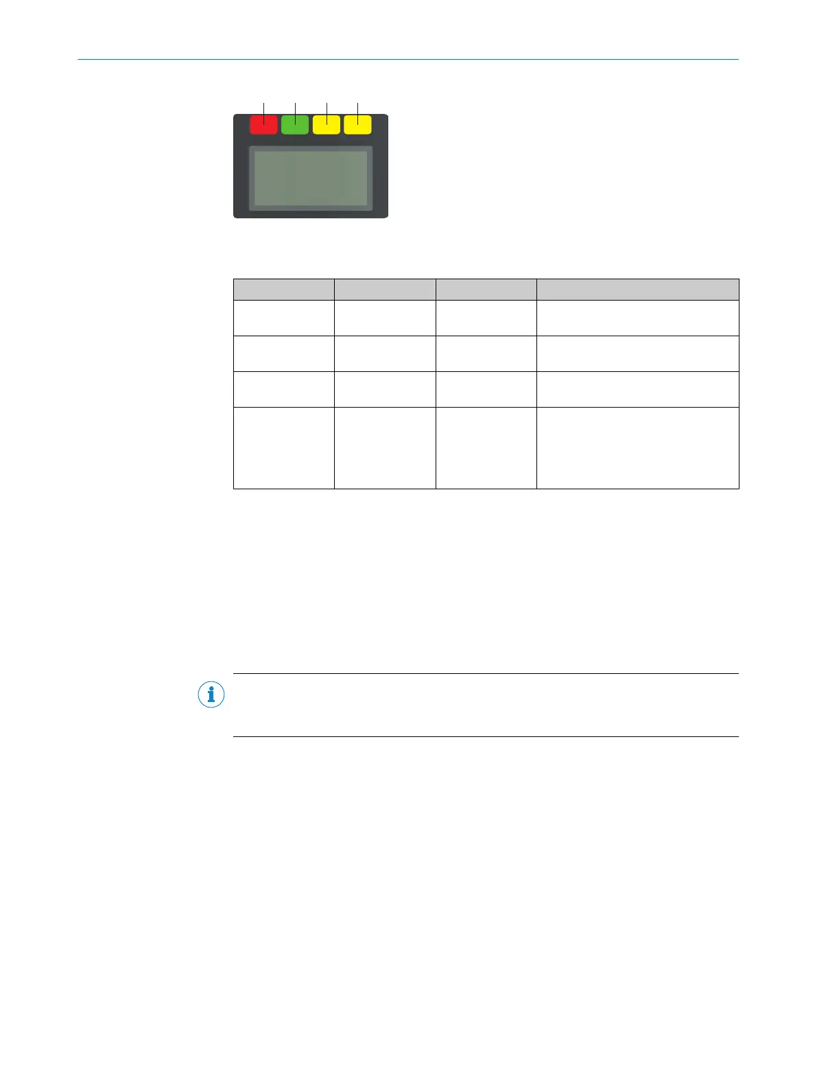
Figure 78: Status LEDs
T
able 17: Status LEDs
Number Function Color Meaning
1
OFF state Red Lights up red when at least one
s
afety output is in the OFF state.
2
ON state Green Lights up green when at least one
s
afety output is in the ON state.
3
Warning field Yellow Shines yellow if at least one warning
field is interrupted.
4
Restart interlock Yellow Setup with reset: Flashes if the
restart interlock has been triggered.
Configuration with automated restart
after a time: Lights up while the con‐
figured time to restart expires.
The OFF state and ON state light emitting diodes can be found in multiple locations on
t
he safety laser scanner. 3 additional sets are arranged in pairs on the base of the
optics cover. So the light emitting diodes can also be seen in many cases when it is not
possible to see the display, e.g. due to the mounting situation or because it is hidden
from the operator’s position.
9.4 Buttons and display
The safety laser scanner is equipped with 4 pushbuttons and a graphical display. You
c
an use the buttons to show information on the display and make simple settings.
NOTE
T
he display language is set using Safety Designer during configuration. The display lan‐
guage and the configuration cannot be changed using the buttons on the display.
9 OPERATION
122
O P E R A T I N G I N S T R U C T I O N S | microScan3 – EFI-pro 8021913/15ZW/2019-11-14 | SICK
Subject to change without notice