The functional earth must be connected via one, and only one of the available FE con‐
nec
tions:
•
Pin on the M12 plug connector
•
Thread on the M12 plug connector
•
Alternative FE connection
The functional earth must be connected in a low-inductance manner and with an ade‐
quate cross-section while keeping the cable length as short as possible. Functional
earth and protection earth must be isolated.
Older system plugs (older than roughly September 2019) might not have an alternative
FE c
onnection.
6.3.3 Ethernet for EFI-pro, data output, configuration, and diagnostics (XF1, XF2)
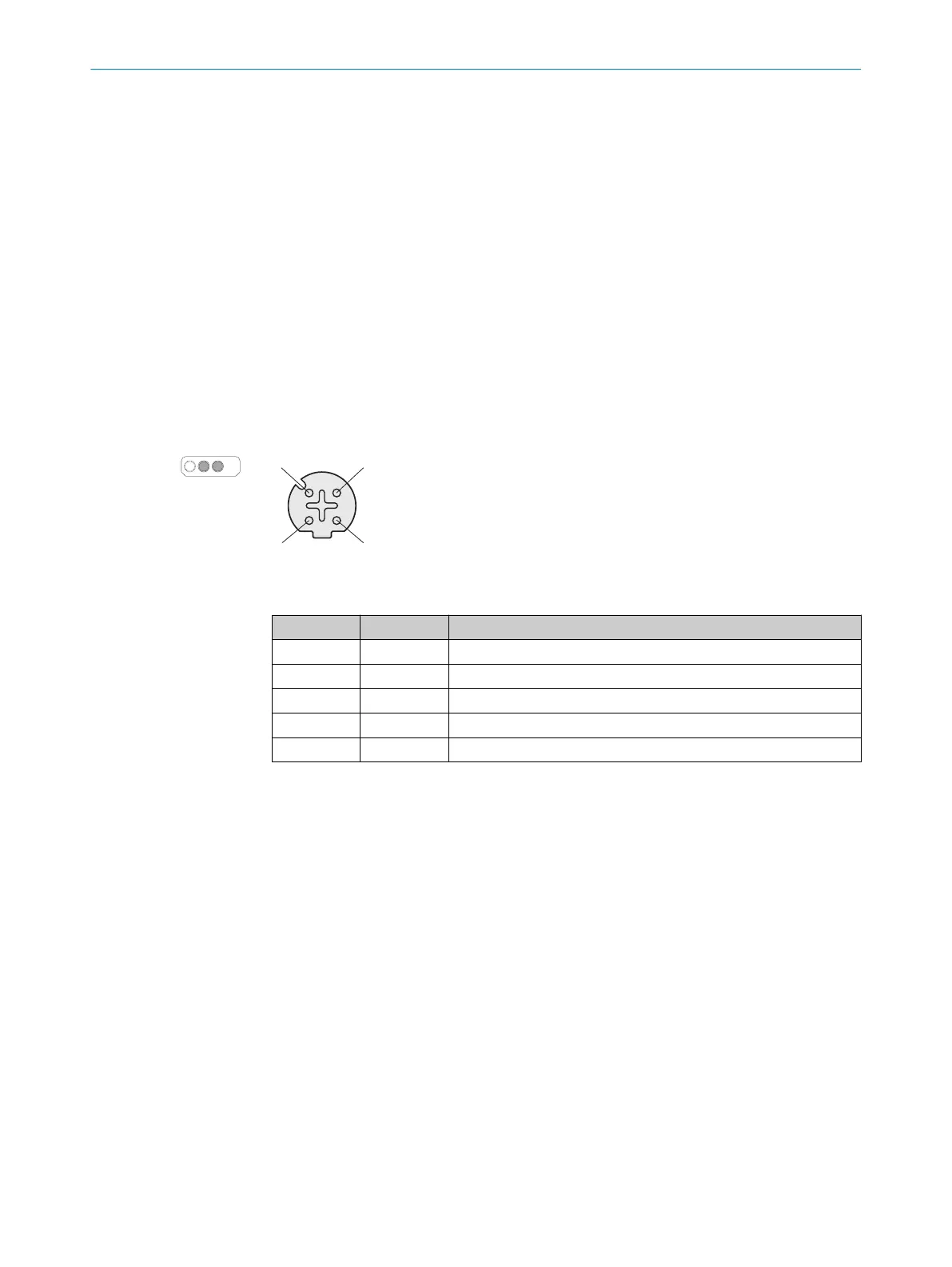
On the device side, Ethernet and EFI-pro are connected via 4-pin, D-coding M12 female
c
onnectors. There is a network switch in the safety laser scanner which connects the
two Ethernet female connectors. The two Ethernet female connectors therefore have
the same function. The pin assignment corresponds to EN 61918, Appendix H.
Figure 53: Ethernet pin assignment (female connector, M12, 4-pin, D-coding)
Table 8: Ethernet pin assignment
Pin Designation Function
1 TX+ Send data +
2 RX+ Receive data +
3 TX– Send data -
4 RX– Receive data -
Thread SH Shielding
ELECTRICAL INSTALLATION 6
8021913/15ZW/2019-11-14 | SICK O P E R A T I N G I N S T R U C T I O N S | microScan3 – EFI-pro
73
Subject to change without notice