•
T
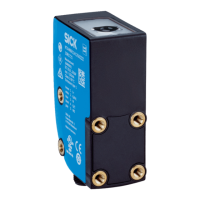
he front is the side of the safety laser scanner on which the display is located.
The 90° angle of the sector of a circle scanned by the safety laser scanner points
in this direction.
•
The back is the side of the safety laser scanner opposite the display. The sector of
a circle not scanned by the safety laser scanner lies in this direction.
3.2.2 Variants
The safety laser scanner is delivered in different variants. You will find an overview of
im
portant distinguishing features of the variants in the following.
Performance package
The Core and Pro performance packages feature a number of configurable fields and a
number of safety switching functions.
•
microScan3 Core – EFI-pro
•
microScan3 Pro – EFI-pro
Integration in the control
T
he safety laser scanner communicates with the SICK safety controller as follows:
•
EFI-pro
EFI-pro
1)
is an Ethernet-based network for general and safety-related data communica‐
tion.
Devices can exchange data via EFI-pro, such as control signals, safety-related shut-off
signals, and diagnostics data.
Protective field range
T
he safety laser scanner is available in variants with the following maximum protective
field range:
•
4.0 m
•
5.5 m
•
9.0 m
Further topics
•
"Variant overview", page 151
3.2.3 Status indicators
The safety laser scanner outputs important status information using a number of light
emit
ting diodes. The safety laser scanner has a graphical display and 4 pushbuttons for
additional information.
4 status light emitting diodes are located directly above the display.
Figure 5: Status LEDs
1)
Enhanc
ed Function Interface-pro based on EtherNet/IP™ – CIP Safety™.
3 P
RODUCT DESCRIPTION
16
O P E R A T I N G I N S T R U C T I O N S | microScan3 – EFI-pro 8021913/15ZW/2019-11-14 | SICK
Subject to change without notice
 Loading...


