EasyManuals Logo

SICK microScan3 - EFI-pro User Manual

SICK microScan3 - EFI-pro
192 pages
To Next Page IconTo Next Page
To Previous Page IconTo Previous Page
Page #52 background imageLoading...
Page #52 background image
190 mm
150 mm
S
L
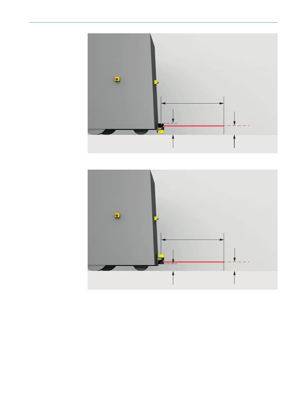
Figure 37: Recommended fitting height
110 mm
150 mm
S
L
Figure 38: Recommended fitting height for inverted mounting
4.4 Integrating the equipment into the electrical control
This chapter contains important information about integration in the electrical control.
Inf
ormation about the individual steps for electrical installation of the device: see "Elec‐
trical installation", page 71.
Information about pin assignment: see "Pin assignment", page 72.
Requirements for use
The protective device delivers safety-related shut-off signals via the network. Reliable
evaluation and switch-off of the machine must be realized in a control suitable for EFI-
pro.
4 PROJECT PLANNING
52
O P E R A T I N G I N S T R U C T I O N S | microScan3 – EFI-pro 8021913/15ZW/2019-11-14 | SICK
Subject to change without notice

Table of Contents

Questions and Answers:

Question and Answer IconNeed help?

Do you have a question about the SICK microScan3 - EFI-pro and is the answer not in the manual?

SICK microScan3 - EFI-pro Specifications

General IconGeneral
Scanning angle275°
Number of fieldsUp to 128
Number of monitoring casesUp to 128
Enclosure ratingIP65, IP67
Number of protective fieldsUp to 128
Field setsUp to 128
Protective field range5.5 m
Resolution30 mm / 40 mm / 50 mm / 70 mm / 150 mm
InterfaceEthernet/IP, PROFINET
Ambient operating temperature0 °C ... +50 °C
Scanning range5.5 m (protective)
Safety integrity levelSIL3 (IEC 61508)
Performance levelPL e (ISO 13849)
TypeType 3
Detection capability30 mm
Operating voltage19.2 V DC to 30 V DC
Ambient temperature0°C to +50°C
Storage temperature-25 °C ... +70 °C
Housing materialAluminum
ConnectionM12 connector
Safety standardsIEC 61496-1, IEC 61508, ISO 13849

Related product manuals