•
C
ontour detection field
•
Warning field
Table 3: Field types and their function
Protective field Reference con‐
t
our field
Contour detec‐
tion field
Warning field
Safe switch off
(ac
cording to ISO
13849-1)
Yes (PL d) Yes (PL d) Yes (PL d) No
Max. scanning
range of the
safety laser scan‐
ner
Variant-depen‐
dent:
4.0 m
5.5 m
9.0 m
Variant-depen‐
dent
:
4.0 m
5.5 m
9.0 m
Variant-depen‐
dent
:
4.0 m
5.5 m
9.0 m
Variant-depen‐
dent
:
40 m
64 m
Purpose Detection and
pr
otection of peo‐
ple
Tamper protec‐
tion
e.g. door monitor‐
ing
Functional use
(no safety-rele‐
vant use)
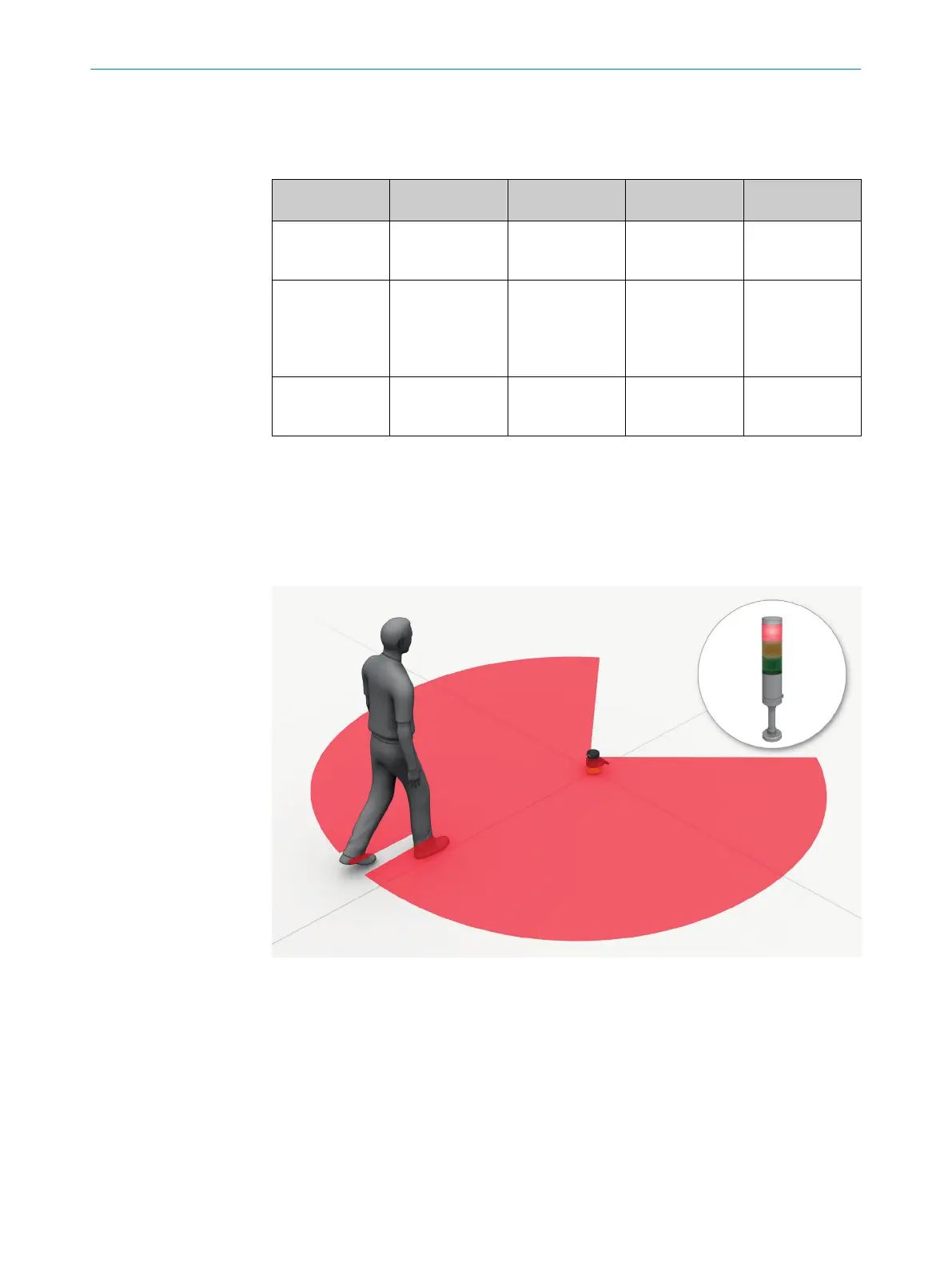
Protective field
T
he protective field protects the hazardous area of a machine or vehicle. As soon as the
electro-sensitive protective device detects an object in the protective field, it switches
the associated safety outputs to the OFF state. This signal can be passed to controllers
resulting in the dangerous state coming to an end, e.g. to stop the machine or the vehi‐
cle.
Figure 6: Protective field, shown in red in this document
Reference contour field
T
he reference contour field monitors a contour of the environment. The safety laser
scanner switches all safety outputs to the OFF state if a contour does not match the set
parameters, because, for example, the mounting situation of the safety laser scanner
were changed.
National and international standards require or recommend that a reference contour is
monitored, if the safety laser scanner is used in vertical operation for hazardous point
protection or for access protection.
3 P
RODUCT DESCRIPTION
18
O P E R A T I N G I N S T R U C T I O N S | microScan3 – EFI-pro 8021913/15ZW/2019-11-14 | SICK
Subject to change without notice