Table 7-49 Assignment of connector X62
Pin Signal name Type Meaning
1 P5HW V 5 V power supply
2 M V Ground
3 HW1_A I Handwheel 1 pulses track A
4 HW1_XA I Handwheel 1 pulses track A (negated)
5 HW1_B I Handwheel 1 pulses track B
6 HW1_XB I Handwheel 1 pulses track B (negated)
7 P5HW V 5 V power supply
8 M V Ground
9 HW2_A I Handwheel 2 pulses track A
10 HW2_XA I Handwheel 2 pulses track A (negated)
11 HW2_B I Handwheel 2 pulses track B
12 HW2_XB I Handwheel 2 pulses track B (negated)
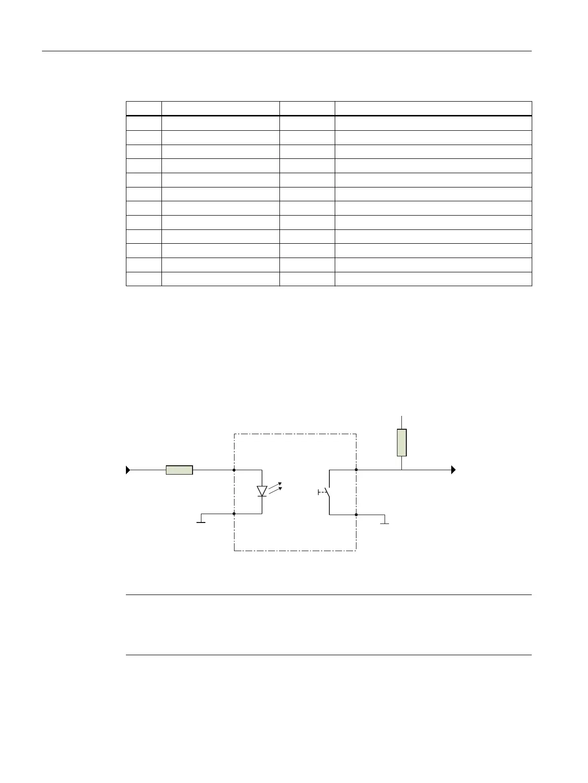
Digital inputs and outputs X111, X112, X113, X114
You can connect up to 80 keys and 64 LEDs. The connectors are connected to the machine
control panel with ribbon cables.
All keys signal "high" in the idle state (= open). When actuated, the state changes to "low".
Short-stroke keyboards and membrane keyboards can be connected. 5 V signals can also be
applied to the inputs. The inputs are TTL-compatible, but not 24 V-tolerant.
.H\
/('
0DFKLQHFRQWUROSDQHO
5S
0
0
',
N˖
39
;
;
;
˖
;
'2
Figure 7-33 Schematic circuit diagram X111
Note
LED brightness
The setting of the LED brightness can be implemented by an additional external resistor
connected in series.
Anschließbare Komponenten
7.5 MCP Interface PN
PPU and components
164 Manual, 05/2015, 6FC5397-2DP40-3BA4

 Loading...


