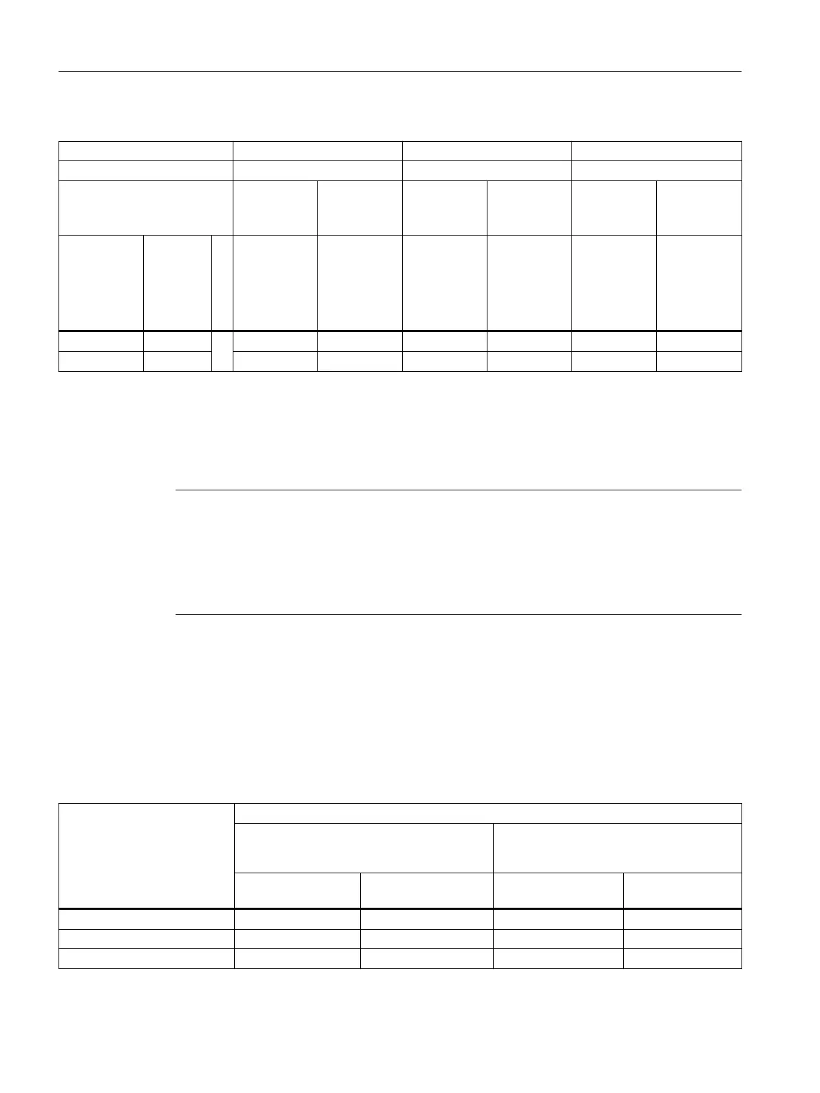
Table 11-10 Type 2N
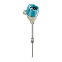
Head type AH0, AV0, SITRANS TF AG0, UG0 AU0, UU0
T
max
head T85 °C 100 °C 120 °C
Max. permitted power con‐
sumption of electronic (W)
0
Without
electronic
1
1)
With elec‐
tronic
0
Without
electronic
1
1)
With elec‐
tronic
0
Without
electronic
1
1)
With elec‐
tronic
Medium
temperature
(°C)
Tempera‐
ture in‐
crease by
Medi‐
um ΔT2D
(K)
T
a_max
in °C T
a_max
in °C T
a_max
in °C T
a_max
in °C T
a_max
in °C T
a_max
in °C
100 °C 10 75 53 100 53 120 53
80 °C 8 85 63 100 63 120 63
1)
Assembled temperature transmitter for example SITRANS TH
11.1.3 Maximum permitted sample temperatures within the process
Note
Permissible ambient temperature at sensor
The maximum permissible ambient temperature at the sensor simultaneously corresponds to
the highest permissible sample temperature.
The minimum permissible sample temperatures are up to -200 °C depending on the version of
the temperature sensor.
See also
Maximum permitted sample temperatures within the process (Page 138)
Resistance thermometers
Table 11-11 RTD temperature sensor (R
th
max=120 K/W)
1 x RTD TF/3 mm/6 mm
2 x RTD TF/3 mm/6 mm
1 x RTD WW/3 mm/6 mm
2 x RTD WW/3 mm/6 mm
Max. permissible sample temperature (°C)
Certied transmitter in Zone 0 with type of
protection "Intrinsically safe"
Certied transmitter in Zone 1, 2 with
type
of protection "Intrinsically safe"
P0: 0 … ≤37 mW
1)
P0: ≥37 … ≤100 mW P0: 0 … ≤37 mW
1)
P0: ≥37 … ≤100
mW
T1 = 450 °C -10K 348 340 436 428
T2 = 300 °C -10K 228 220 286 278
T3 = 200 °C - 5K 152 144 191 183
Technical data
11.1 Rated conditions
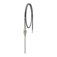
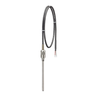
SITRANS TS100/TS200/TS300/TS500/TSinsert/TSthermowell
138 Operating Instructions, 08/2020, A5E47810090-AA