7. With small conduit diameters, mount the sensors against the direction of ow. Angled ② or
in a pipe elbow ③.
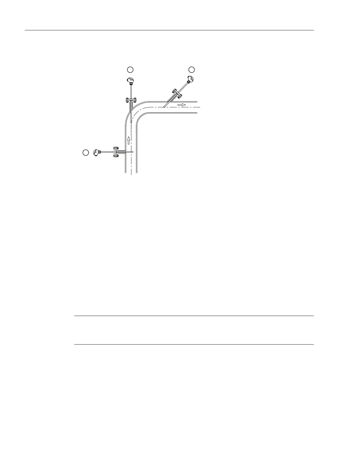
① At a right angle to the ow
② In the pipe elbow against the direction of ow
③ Angled against the direction of ow
Figure 4-2 Possible mounting positions of the sensor
8. Observe the torques required between device extension and conduit Torques between
device extension and conduit (Page 140).
– If customized adaptations are necessary (only M24 connectors), note the required
torques between the device head and extension as specied in Torques between device
head and extension (Page 140).
– When mounting a SITRANS TS500 in full material design type 4 without ange (only
Europe portfolio 7MC752..) of the device extension at the conduit, observe the
required Torques between device extension and conduit (Page 140).
4.3 Mounting SITRANS TS300 in clamp-on design
Note
Measuring position
Only install on round pipes. Avoid an installation close to pipe elbows, sliders, valves, etc.
1. Determine the measuring position on the pipe.
2. Apply the thermal paste on the metal part of the temperature sensor.
3. For the standard design: Install the two sleeving parts to the pipe using two xing screws.
For the clamp design: Mount the SITRANS TS300 using a xing screw.
– If the process medium does not ow through the full cross-section of the pipe, mount the
temperature sensor on the bottom of the pipe.
Installing/mounting
4.3 Mounting SITRANS TS300 in clamp-on design
SITRANS TS100/TS200/TS300/TS500/TSinsert/TSthermowell
32 Operating Instructions, 08/2020, A5E47810090-AA