Scope Multimeter Operation and Controls
85
Channel Settings
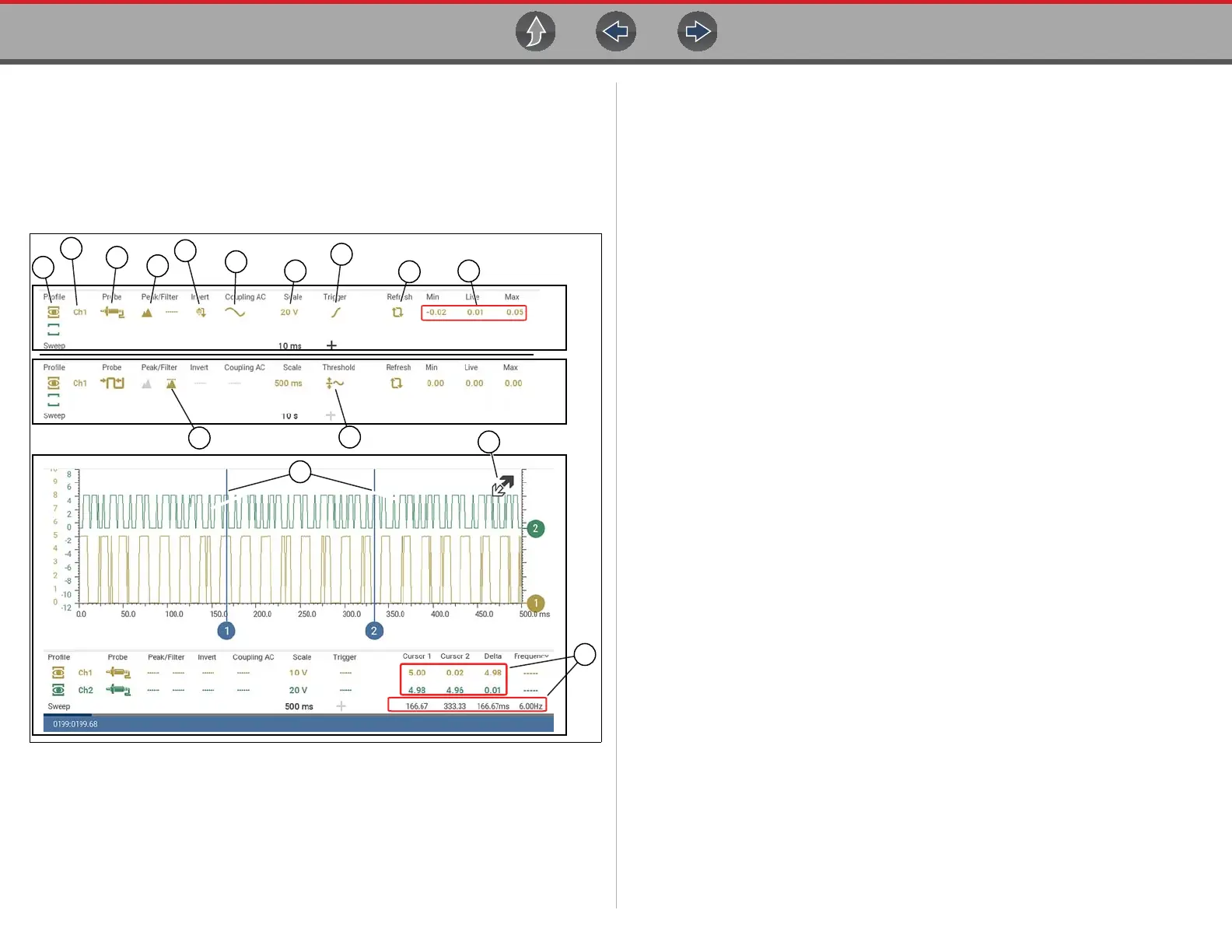
The majority of the channel (trace) settings and controls are located in the Control
Panel. Each setting is represented by an icon, or a value. Icons are used to make
adjustments, and the displayed values represent an individual characteristic.
Depending on the test, applicable settings are displayed. The following image
shows different views of the control panels to identify the different controls.
Figure 9-20
15
16
5
14
1
2
3
4
6
7
8
9
10
11
17
1— Show/Hide (Channel display
on/off)—turns channel on/off
2— Trace (Zero Baseline position
adjustment)—adjusts zero
baseline position
3— Probe (Probe type “test”
selection)—changes test
probe function
4— Peak Detect—maximizes
sampling rate
5— Filter—removes signal noise
or interference
6— Invert—switches signal
polarity
7— Coupling AC—blocks the DC
portion of signal
8— Scale (Vertical scale
adjustment)—adjusts vertical
scale
9— Trigger—turns triggering on/
off, and sets direction of
trigger slope
10—Refresh—clears Min, Max and
Live values and resets to zero
11—Min, Live and Max Display
Panel —displays lowest,
highest and current trace
measurements set since the
test was activated
12—Sweep (Horizontal or Time
scale adjustment)—adjusts
horizontal scale
13—Trigger Position Icon—opens
trigger position control panel
14—Threshold —turns auto
threshold on, to provide a more
accurate measurement on
select tests where noise is
present (GMM only)
15—Cursors—used to measure
time, amplitude and frequency
16—Cursor Measurements Panel—
displays signal amplitude at
cursor and cursor position in
time
17—Expand/Collapse Icon -
Toggles display of the control
panel (Trace Detail)

 Loading...