133
Gefran
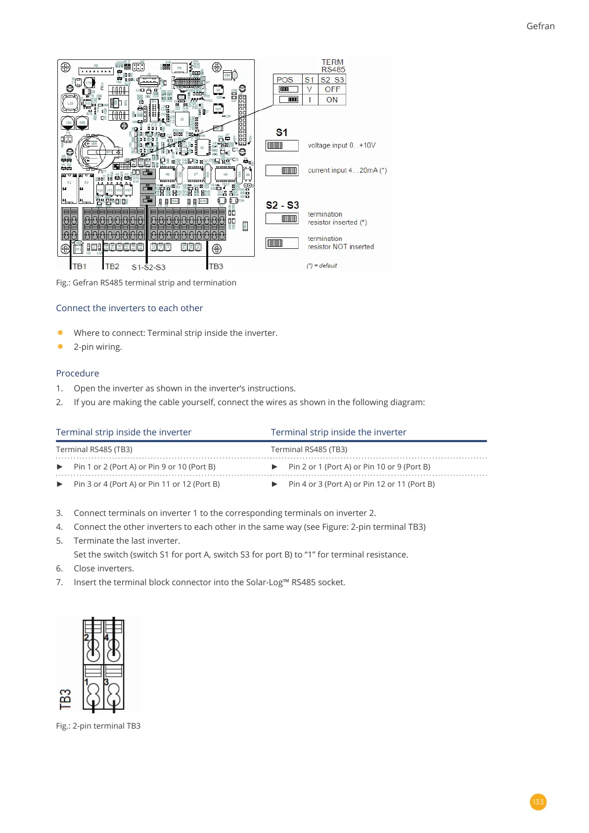
Fig.: Gefran RS485 terminal strip and termination
Connect the inverters to each other
•
Where to connect: Terminal strip inside the inverter.
•
2-pin wiring.
Procedure
1. Open the inverter as shown in the inverter’s instructions.
2. If you are making the cable yourself, connect the wires as shown in the following diagram:
Terminal strip inside the inverter Terminal strip inside the inverter
Terminal RS485 (TB3) Terminal RS485 (TB3)
► Pin 1 or 2 (Port A) or Pin 9 or 10 (Port B) ► Pin 2 or 1 (Port A) or Pin 10 or 9 (Port B)
► Pin 3 or 4 (Port A) or Pin 11 or 12 (Port B) ► Pin 4 or 3 (Port A) or Pin 12 or 11 (Port B)
3. Connect terminals on inverter 1 to the corresponding terminals on inverter 2.
4. Connect the other inverters to each other in the same way (see Figure: 2-pin terminal TB3)
5. Terminate the last inverter.
Set the switch (switch S1 for port A, switch S3 for port B) to “1” for terminal resistance.
6. Close inverters.
7. Insert the terminal block connector into the Solar-Log™ RS485 socket.
Fig.: 2-pin terminal TB3