295
SMA
Connect inverters to the Solar-Log™
•
The wiring is done using a
ready-made data cable (optional extra; not supplied)
or
self-made, shielded 4 wire data cable and terminal block connector.
Procedure
1. Pull the free wires through the wire opening in the inverter.
2. If you are making the cable yourself, connect the wires as shown in the following diagram:
Solar-Log™ terminal strip connector Inverter terminal strip
Terminal Terminal
► 1 ► 2
► 2 ► 3
► 3 ► 5
► 4 ► 7
3. Pull the wire in the inverter through the insulation sleeve attached to the piggy back.
The wire must be enclosed in the insulating hose inside the inverter.
4. Ground the connection: Connect terminal 5 on the inverter to the inverter housing using the supplied flat strip
connector.
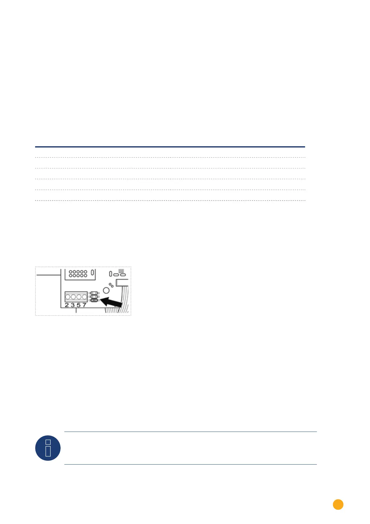
If only one inverter is to be connected it must be terminated.
Put the supplied jumper onto the lower pins on the connector strip.
Fig.: Piggyback - insert jumper
5. Close the inverter if no other inverters are to be connected.
6. Insert the terminal block connector into the Solar-Log™ RS485 socket.
Connect the inverters to each other
•
Connect using a 4 wire, shielded data cable (e.g. a 25 m ring cable, Solare Datensysteme order 220014)
•
Where to connect: Terminal block in inverter (on the retrofitted RS485 interface)
Procedure
1. Pull the wire in the inverter through the insulation sleeve attached to the piggy back
The wire must be enclosed in the insulating hose inside the inverter.
2. Connect all 4 contacts (2, 3, 5, 7) on the terminal strip of inverter 1 to inverter 2
Note
A diagram for wiring in SMA combined mode can be found in the appendix.