410
Solar-Log™ PRO
4 Solar-Log™ PRO
4.1 Solar-Log™PRO1Mod(singlephase)
Selections available under „Solar-Log/Pro/RS485“
Supported by firmware 4.1.0 and higher
Overview
•
The communication address has to be assigned.
•
2-pin wiring.
•
Installation steps:
• Switch off the meter and the Solar-Log™.
• Connect the meter to the Solar-Log™.
Note
The communication address is set to 1 by default, but can be adjusted
if several meters are connected to one RS485 bus.
Maximum of 60 meters per RS485 bus.
Connect the meter to the Solar-Log™
The wiring is done using a
•
self-made cable connection with a terminal block connector.
4.1.1 Connectiondiagram
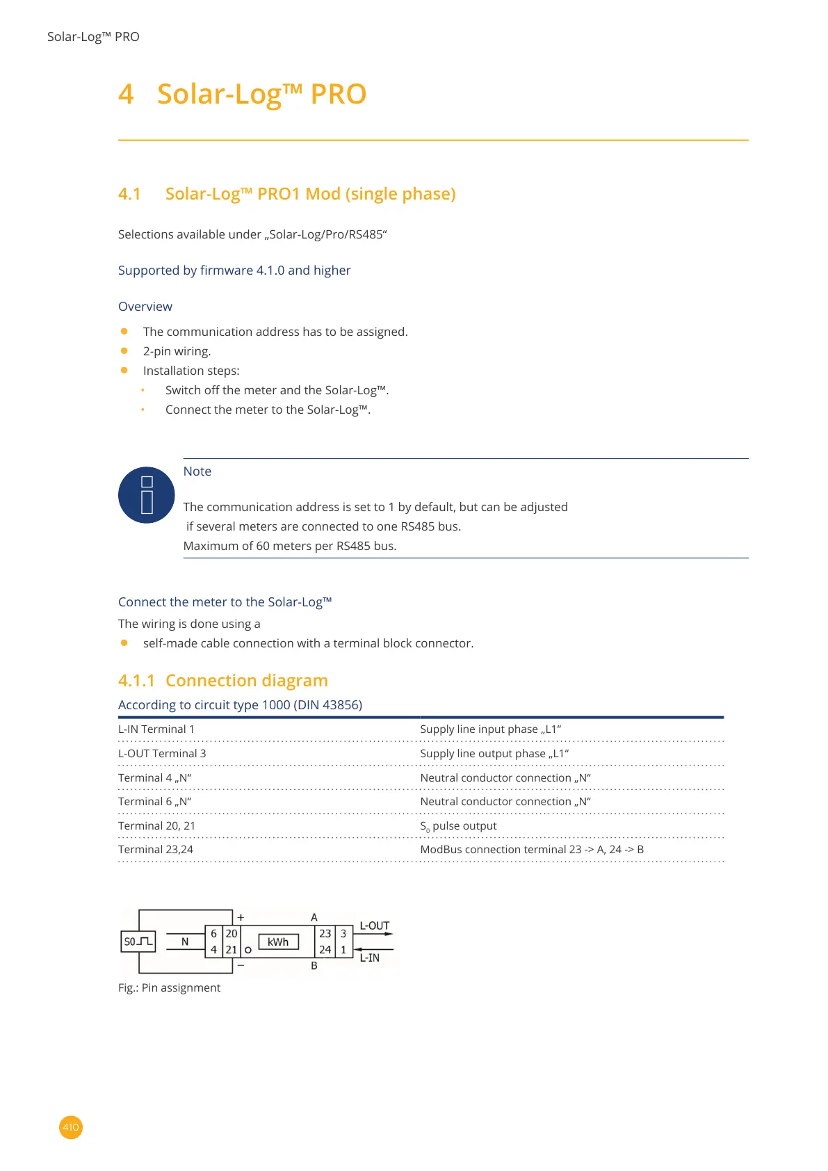
According to circuit type 1000 (DIN 43856)
L-IN Terminal 1 Supply line input phase „L1“
L-OUT Terminal 3 Supply line output phase „L1“
Terminal 4 „N“ Neutral conductor connection „N“
Terminal 6 „N“ Neutral conductor connection „N“
Terminal 20, 21 S
0
pulse output
Terminal 23,24 ModBus connection terminal 23 -> A, 24 -> B
Fig.: Pin assignment