285
Siemens
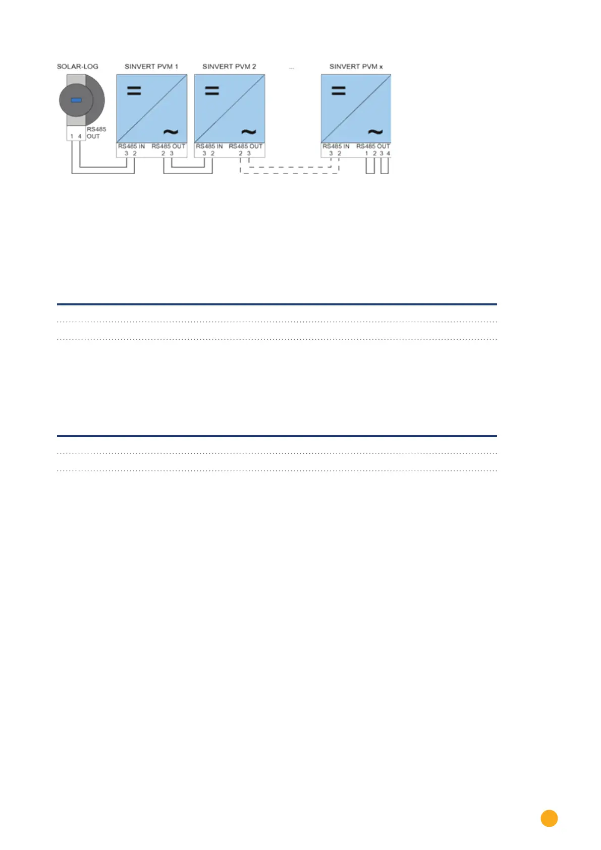
Fig.: Siemens – connecting inverters together
Use the SACC-M12MS-4SC connectors supplied with the inverter for data cables.
•
Connect them as shown in the diagram.
•
Connect the bus cable on the last inverter to the RS485 OUT socket using a terminal resistor.
Inverter - RS485 OUT
(4-pin round plug)
Inverter - RS485 IN
(4-pin round plug)
Pin 2 Pin 2
Pin 3 Pin 3
Bus termination
The bus must be terminated on the RS485 OUT connection of the last inverter with 120Ω.
To do this use the internal 120 Ω resistor and wire the following pins in a round 4-pin plug with two jumpers.
Inverter - RS485 OUT (4-pin round plug)
Pin 1 Pin 2
Pin 3 Pin 4
•
Insert this plug into the RS485 OUT socket of the last inverter.
Setting parameters
•
Parameters are set using the display on the inverter.
•
The date and time must be correctly set and the password "72555" entered before the communication set-
tings.
•
The communication parameters are set in the sub-menu
"F1 -> Configuration -> Communication -> RS 485."
•
The individual menu items are selected with the arrow keys ↑↓ and confirmed by pressing ENTER.
•
A consecutive communication address must be allocated to each SINVERT PVM. It is advisable to arrange the
addresses consecutively beginning with 1, i.e. 1, 2, 3 up to a maximum of 31. The Solar-Log™ has address "0".
•
The baud rate should be set to 57600. Baud rate 9600 must only be used when using the wireless package.