62
Aten
11 Aten
11.1 Aten
Termination Addressing Interface
- No RS485
Overview
•
Integrated interface.
•
Where to connect: RJ14 socket on the outside of the inverter.
•
2-pin wiring.
•
Communication address does not have to be assigned.
Installation steps
•
Switch off the inverters and Solar-Log™.
•
Connect inverters to the Solar-Log™.
•
Connect the inverters to each other.
Connect inverters to the Solar-Log™
The wiring is done using a
self-made, shielded 2 wire data cable and terminal block connector
.
Procedure
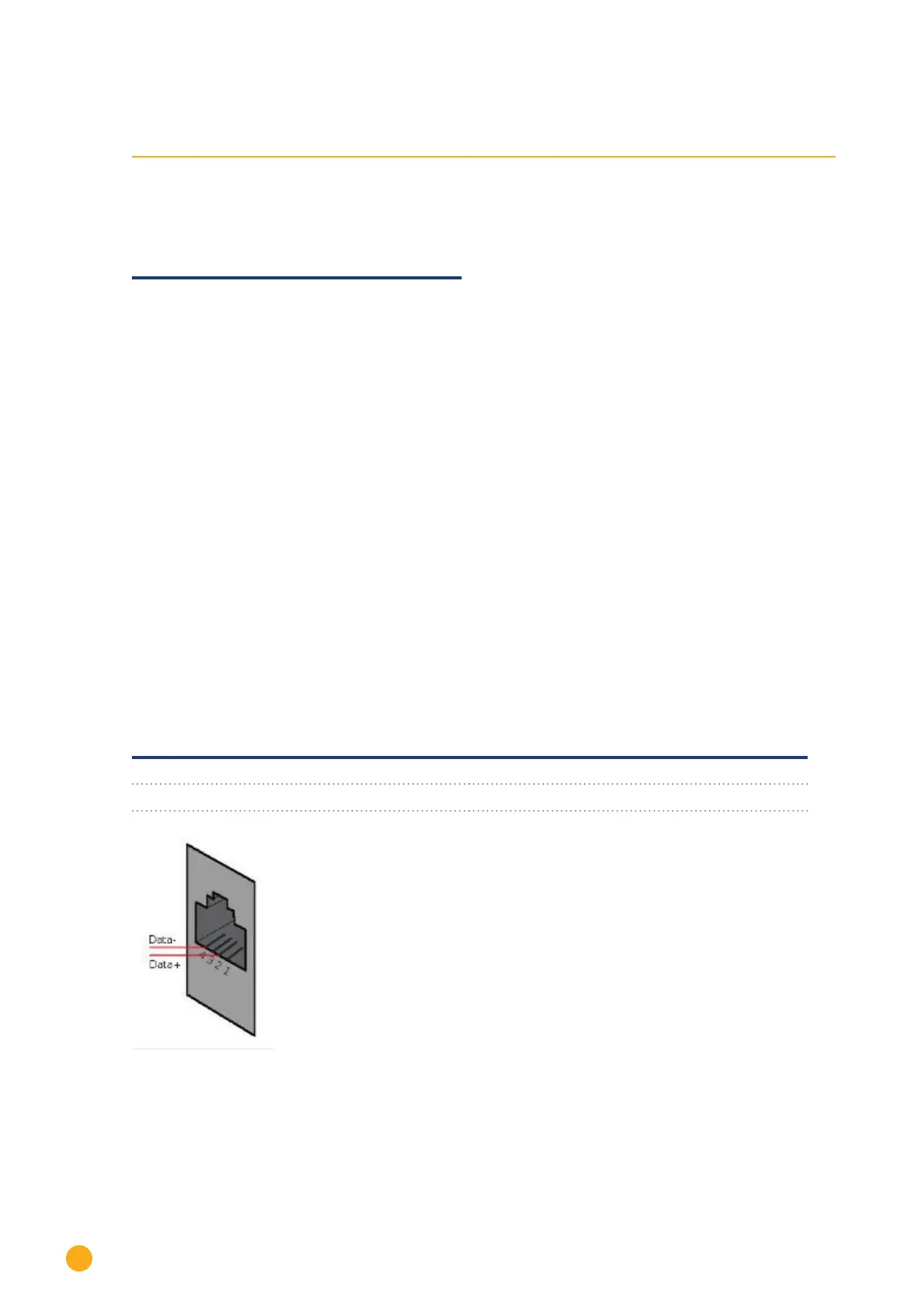
1. If you are making the cable yourself, connect the wires as shown in the following diagram
Solar-Log™ terminal strip connector Inverters
RS485/422 B RJ 14 socket
► 1 ► Pin 2 - Data +
► 4 ► Pin 4 - Data -
Fig.: RJ14 socket pin allocation
2. Close the inverter if no other inverters are to be connected.
3. Insert the terminal block connector into the Solar-Log™ RS485 socket.