294
SMA
84.2 SMAconnectionusingspecialRS485piggybackcard
Termination Addressing Interface
Jumper No RS485
Select “SMA: Data1“ for the device detection.
Overview
•
Interface not integrated; retrofit the special RS485 piggyback card
•
Where to connect: Terminal strip inside the inverter on the piggyback
•
Communication address does not have to be assigned
•
4-pin wiring
•
Installation steps
• Switch off the inverters and Solar-Log™
• Installing the special RS485 piggyback in inverters
• Connect inverters to the Solar-Log™
• Connect the inverters to each other
Installing the special RS485 piggyback in inverters
Procedure
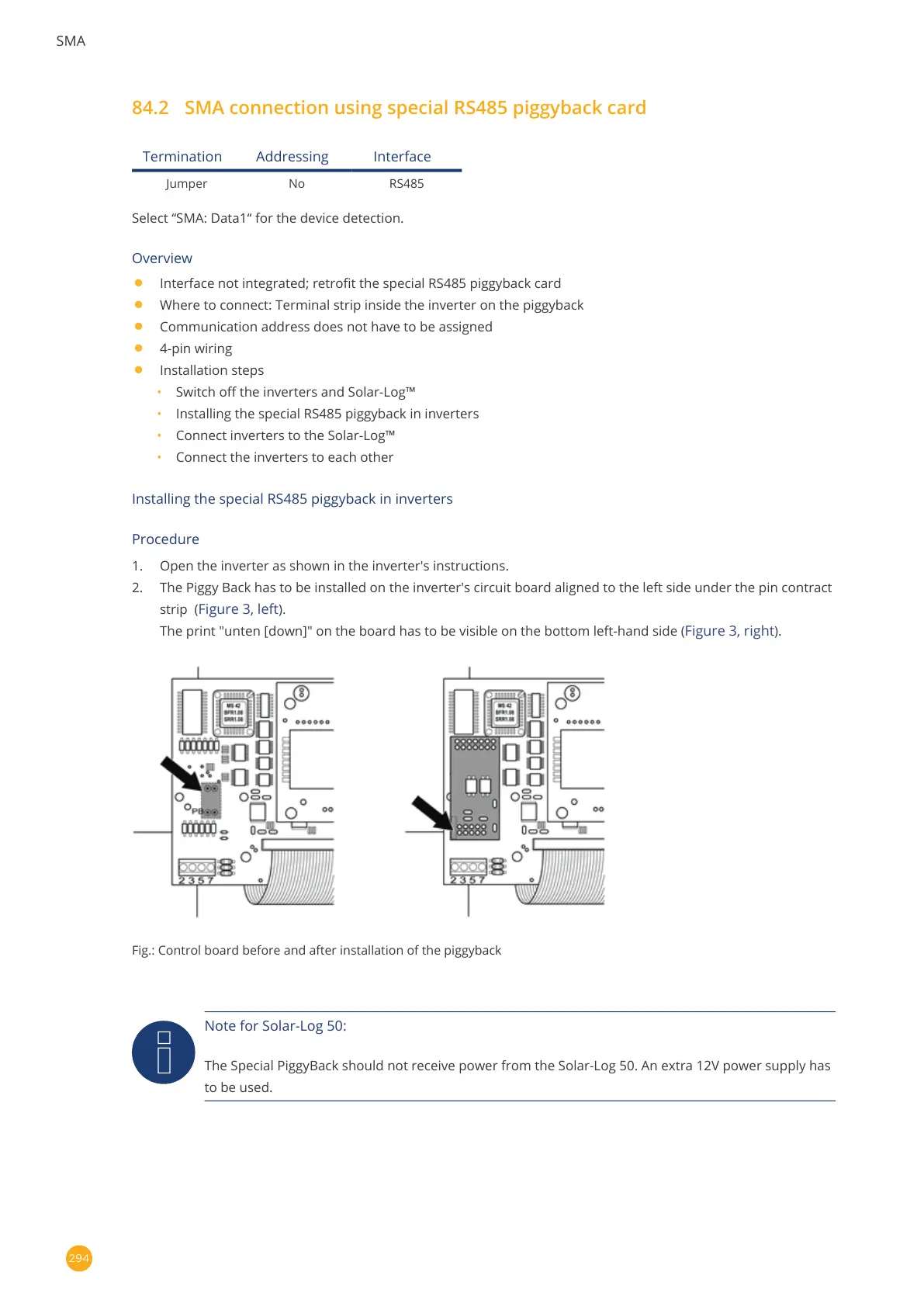
1. Open the inverter as shown in the inverter's instructions.
2. The Piggy Back has to be installed on the inverter's circuit board aligned to the left side under the pin contract
strip (
Figure 3, left).
The print "unten [down]" on the board has to be visible on the bottom left-hand side (
Figure 3, right).
Fig.: Control board before and after installation of the piggyback
Note for Solar-Log 50:
The Special PiggyBack should not receive power from the Solar-Log 50. An extra 12V power supply has
to be used.