417
Solar-Log™ PRO
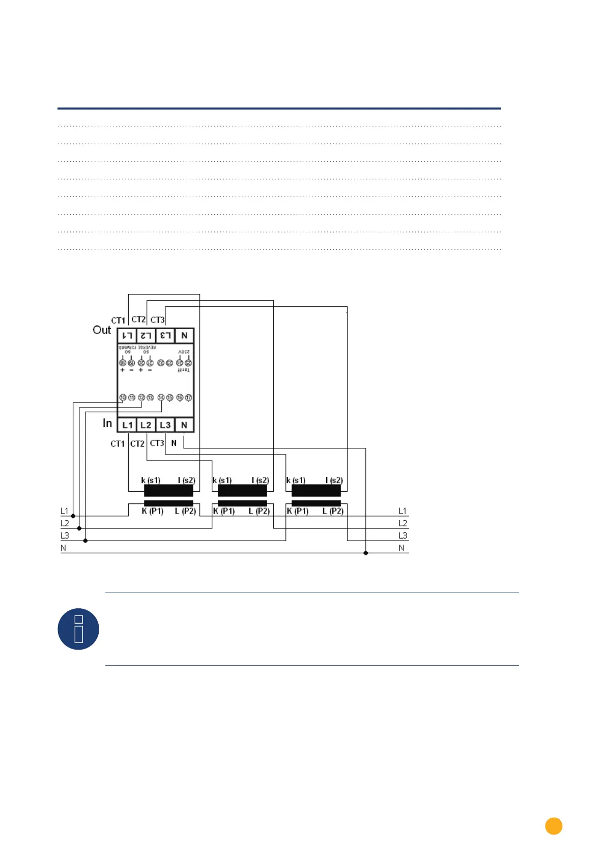
4.3.1 Connectiondiagram
according to circuit type 1000 (DIN 43856)
CT 1 (in) terminal k (s1) / (out) terminal l (s2) 10 Volts Phase 1 (10/11 internally bridged)
CT 2 (in) terminal k (s1) / (out) terminal l (s2) 12 Volts Phase 2 (12/13 internally bridged)
CT 3 (in) terminal k (s1) / (out) terminal l (s2) 14 volts phase 3 (14/15 internally bridged)
Terminal "N" Neutral conductor connection "N"
Terminal 18, 19 S
o
pulse output "FORWARD" (terminal 18 = "+")
Terminal 20, 21 S
o
pulse output "REVERSE" (terminal 20 = "+")
Terminal 22, 23 ModBus connection terminal 22 -> A, 23 -> B
Terminal 24, 25 External tari switching (230V AC)
The SO signal for the supply is not used when a meter is
connected to the Solar-Log™.
Fig.: Pin assignment
Note
We recommend using a fuse to safeguard the connection lines for the voltage measurement in
accordance with the local laws and regulations and with appropriate isolating switches and overload
protection devices.