EasyManua.ls Logo

Staubli CS8C User Manual

Staubli CS8C
248 pages
To Next Page IconTo Next Page
To Previous Page IconTo Previous Page
Page #108 background imageLoading...
Page #108 background image
© Stäubli 2009 – D28070504A CS8C108 / 248
5.10.4. CONFIGURATION OF SYSTEM INPUTS/OUTPUTS
System Inputs/Outputs are configured in the /usr/configs/iomap.cf file. Each CS8C controller is supplied with an
example /usr/configs/iomapExample.cf in which the configurations are commented out. To activate a
configuration, it is necessary to:
Rename the iomapExample.cf file as iomap.cf
Remove the "//" comments in front of the key words to be configured and replace the description after
the "=" by the name of an Input/Output. For example: enablePower = usrIn0
Restart the CS8C
Any configuration errors in the iomap.cf file are listed in the events logger on start-up.
Configuration of system inputs
Certain CS8C functions require a user signal for which the default wiring can be reprogrammed:
When the MCP is replaced by its shorting plug, it is possible to simulate pressing certain keys using inputs:
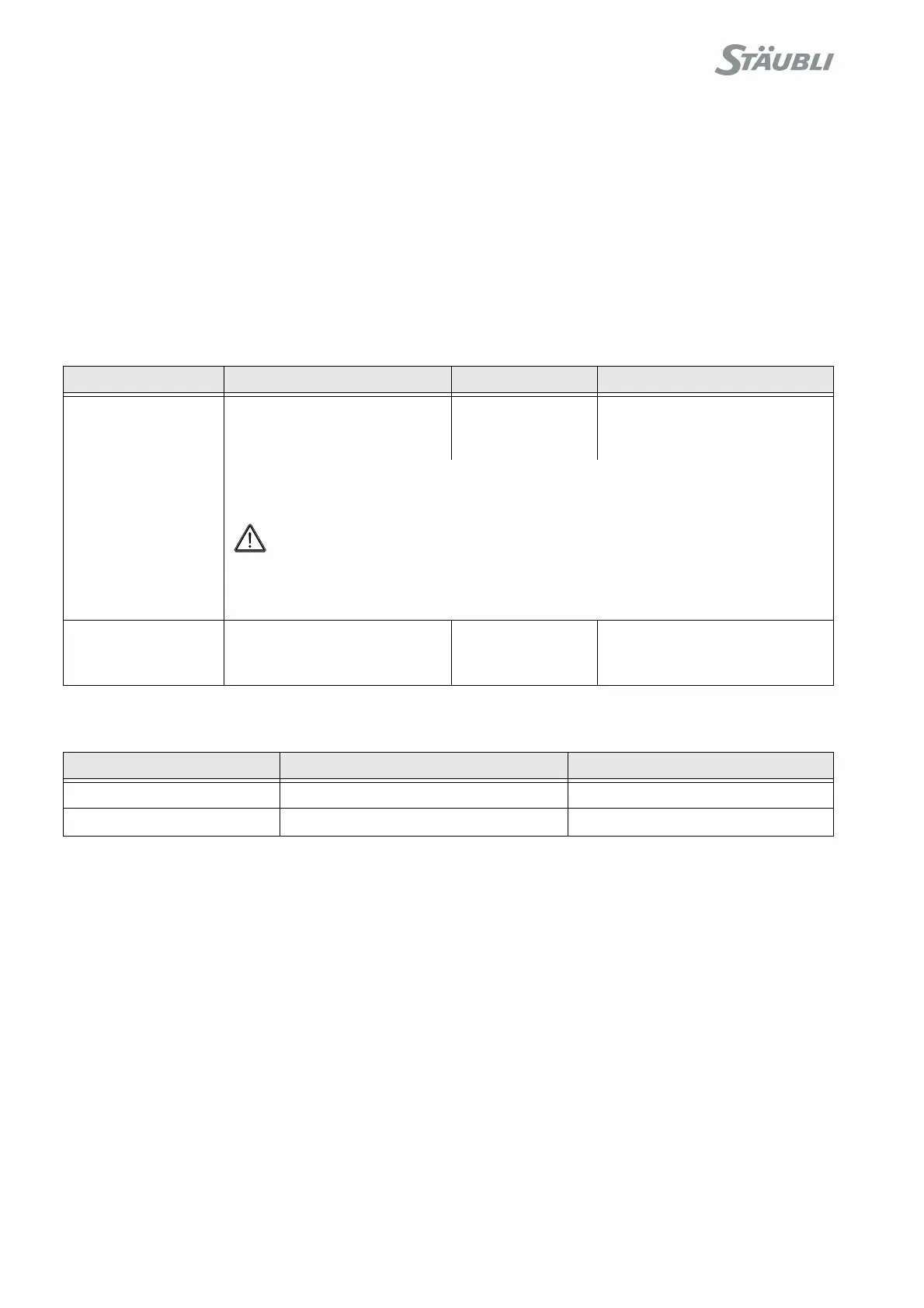
Key word Description Type Default wiring
estopAcknowledge Acknowledgement of the
emergency stop in manual
mode
Digital input Internal signal concerning
detection of the MCP on its
holder
The emergency stop is acknowledged if this signal is activated when the arm is
powered on.
DANGER:
Current standards require that power must be switched on from outside the cell
after an emergency stop. This digital input must thus be linked to an item of
equipment outside the cell.
enablePower Signal that the system has
been powered on in remote
mode (see chapter 6.6.3)
Digital input No wiring
Key word Description Type
remoteMonitorSpeed Monitor speed selection [0, 100] Analog input
remoteMoveHold Replacement of the Move/Hold button Digital input

Table of Contents

Question and Answer IconNeed help?

Do you have a question about the Staubli CS8C and is the answer not in the manual?

Staubli CS8C Specifications

General IconGeneral
Number of AxesUp to 6
Programming LanguageVAL3
Protection ClassIP 54
Humidity5 to 95% non-condensing
Compatible RobotsStaubli robots
Communication InterfacesEthernet, Serial, Fieldbus
SafetySafety PLC integration
Operating Temperature0 to 45°C
Storage Temperature-20°C to 60°C

Summary

Chapter 2 Description of the Controller

2.2. LOCATION AND DESCRIPTION OF THE MAIN COMPONENTS

Describes the CS8C controller, including processor, power amplifiers, and safety boards.

Chapter 3 Safety

3.1. REMINDER CONCERNING THE SAFETY STANDARDS

Outlines safety standards applicable to robots and robot cells, emphasizing compliance and training.

3.2. SAFETY DIRECTIVES CONCERNING TO THE WORK ENVIRONMENT

Covers safety considerations for the robot cell environment and work area.

3.3. SAFETY DIRECTIVES CONCERNING TO STAFF PROTECTION

Addresses mechanical and electrical dangers, and safety measures for personnel.

Chapter 4 Installation

4.2. ON-SITE PREPARATION

Covers electrical and pneumatic network requirements, work environment, and controller mounting.

4.6. CONNECTIONS

Covers connections to the mains power supply, arm, and signals, including cable management.

Chapter 5 Integration

5.1. EMERGENCY AND SAFETY STOP CHANNELS

Describes the composition and connection of emergency and safety stop channels.

5.7. PROGRAMMABLE LOGIC CONTROLLER (PLC OPTION)

Details PLC option installation, operation, programming, and debugging.

Chapter 6 Operation

6.1. POWERING UP THE CONTROLLER

Provides instructions on how to safely power up the controller.

6.2. PRESENTATION OF THE MCP

Details the general presentation, control keys, and display of the Manual Control Pendant (MCP).

6.3. ARM POWER-UP

Explains the procedure for powering up the robot arm safely.

6.4. EMERGENCY STOP

Describes the emergency stop function and the procedure to restore power.

6.5. CALIBRATION, ADJUSTMENT, RECOVERY

Covers definitions, recovery procedures, and adjustment procedures for arm calibration.

6.7. JOG INTERFACE

Explains the jog interface for manual control, movement modes, and point teaching.

Chapter 8 MAINTENANCE

8.4. SAFETY

Reiterates safety precautions, including disconnecting power and handling components.