© Stäubli 2009 – D28070504A CS8C182 / 248
• Remove the 6 screws (1).
• Partially remove the cover (2)
• Remove the connectors J1301 (3), J1303 (4) and the ground wire (5).
• The 4 fans can be accessed by removing the screws (6).
Advanced information
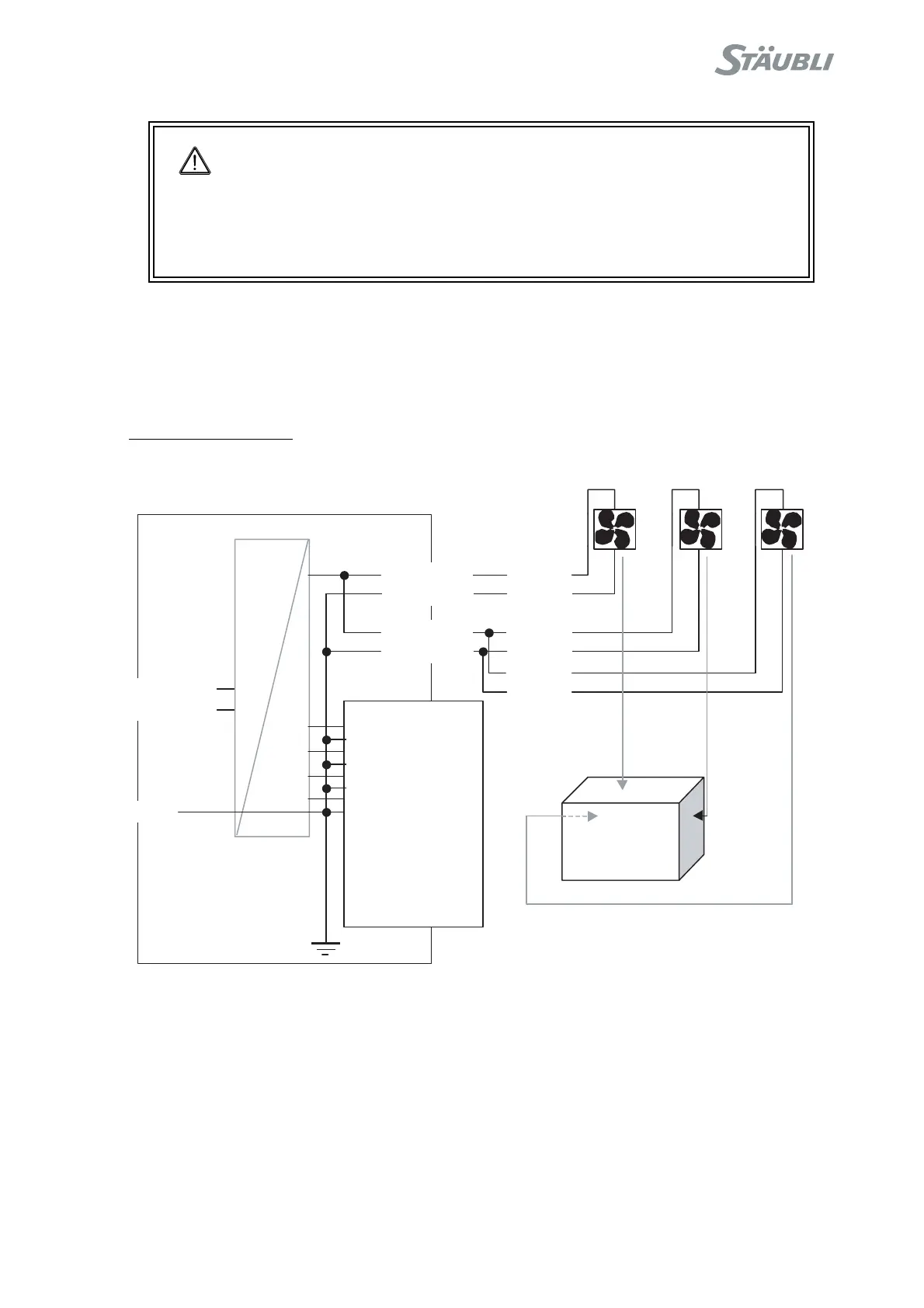
Figure 8.20
DANGER:
• The cover (2), the resistor (8) and the amplifiers (7) may be very hot,
especially in the event of a ventilation malfunction.
• This disassembly operation provides access to the regeneration resistor
powered at 400 V during normal operation. It is essential to cut off all power
supplies before carrying out this operation. Wait for at least 1mn before
starting to work.
ARPS
J11 02
13V 1
0V13 9
24V2 2
0V2 10
24V1 3
0V1 11
24V1 4
0V1 12
ALIM-OK+ 5
ALIM-OK- 13
SECTEUR-OK+ 6
SECTEUR-OK- 14
BRK-REL- EN+ 7
BRK-REL- EN- 15
BRK-ON+ 8
BRK-ON- 16
J1302+
J1302-
J1301-2
J1301-1
x 4
x 3
CS8C
x 1
J1304-1
J1304-2
0V3 J1103-2
24V3 J1103-1
0V3 J1104-2
24V3 J1104-1
J1101-1 Ph2
J1101-2 Ph1
J1101-3
AC
DC
Fan 1 Fan 2 Fan 3