© Stäubli 2009 – D28070504A CS8C18 / 248
2.2. LOCATION AND DESCRIPTION OF THE MAIN COMPONENTS
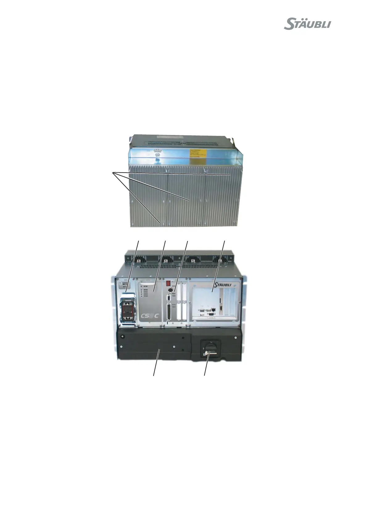
2.2.1. THE CONTROLLER
The CS8C controller is made up of a processor (5), the intelligent part of the installation.
The processor controls the robot via digital power amplifiers (1) dedicated to each axis of the arm.
The electrical power is converted by the PSM (7) power section, the RPS (2) power supply, and the ARPS (3)
power supply which supplies to each of the above elements the voltage required for correct operation from the
mains voltage delivered by the electrical network.
The functions required for electrical safety are grouped together on the RSI (4) board.
Figure 2.2
To disconnect the system from the power supply, set the master switch (6), located on the front panel of the
controller, to 0. Before doing so, you must stop the arm motion and switch off arm power supply.
1
2
3
4
5
76