CS8C © Stäubli 2009 – D28070504A
109 / 248
Chapter 5 - Integration
Access to the system statuses and signals
The status signals for the safety system are set to "On" when an emergency stop has been activated.
CAUTION:
The wiring of the safety system makes it impossible to know the state of each signal when
several eStop signals are activated. The software then returns the last known state.
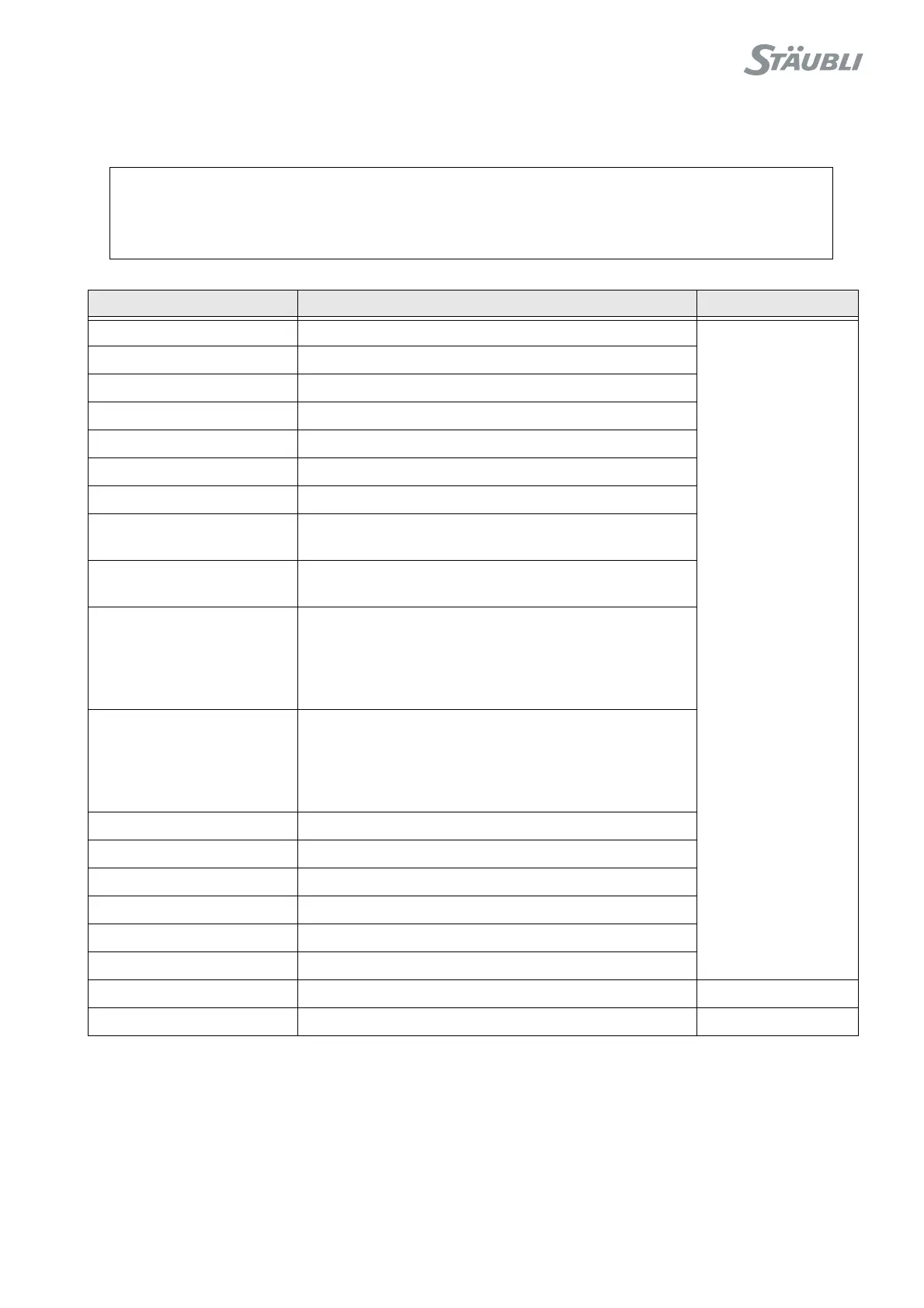
Key word Description Type
limitSwitch Signal that a limit switch has been reached on a joint
Digital output
driveFault Variable speed controller fault signal
initSwitch Software command signal opening the safety system
watchdog Fault signal from the watchdog on the RSI board
fuse24V Status of the 24V supply at fuse F2
estopMCP Emergency stop signal from the MCP
estopWMS Emergency stop signal from the WMS
estopUser1-2 Emergency stop signal from UESA on the safety
system
estopUser3-4 Emergency stop signal from UESB on the safety
system
userEnable Emergency stop signal from USER EN on the safety
system
Caution:
The USER EN signal is not valid in local or remote
mode. Its state is then not updated.
door Emergency stop signal from DOOR on the safety
system
Caution:
The DOOR signal is not valid in manual mode. Its
state is then not updated.
brakeSelect Signal from the joint selector at the base of the arm
brakeRelease Signal requesting brake release at the base of the arm
deadman Status of the MCP enable button
park Signal concerning detection of the MCP on its holder
power Arm power status
dummyPlug Signal that the MCP is replaced with a shorting plug
temperature Temperature (°C) measured on the RSI board Analog output
popup Messages displayed on the MCP Serial port