© Stäubli 2009 – D28070504A CS8C84 / 248
5.5. DIGITAL BIO INPUT/OUTPUT BOARD (OPTIONAL EXTRA)
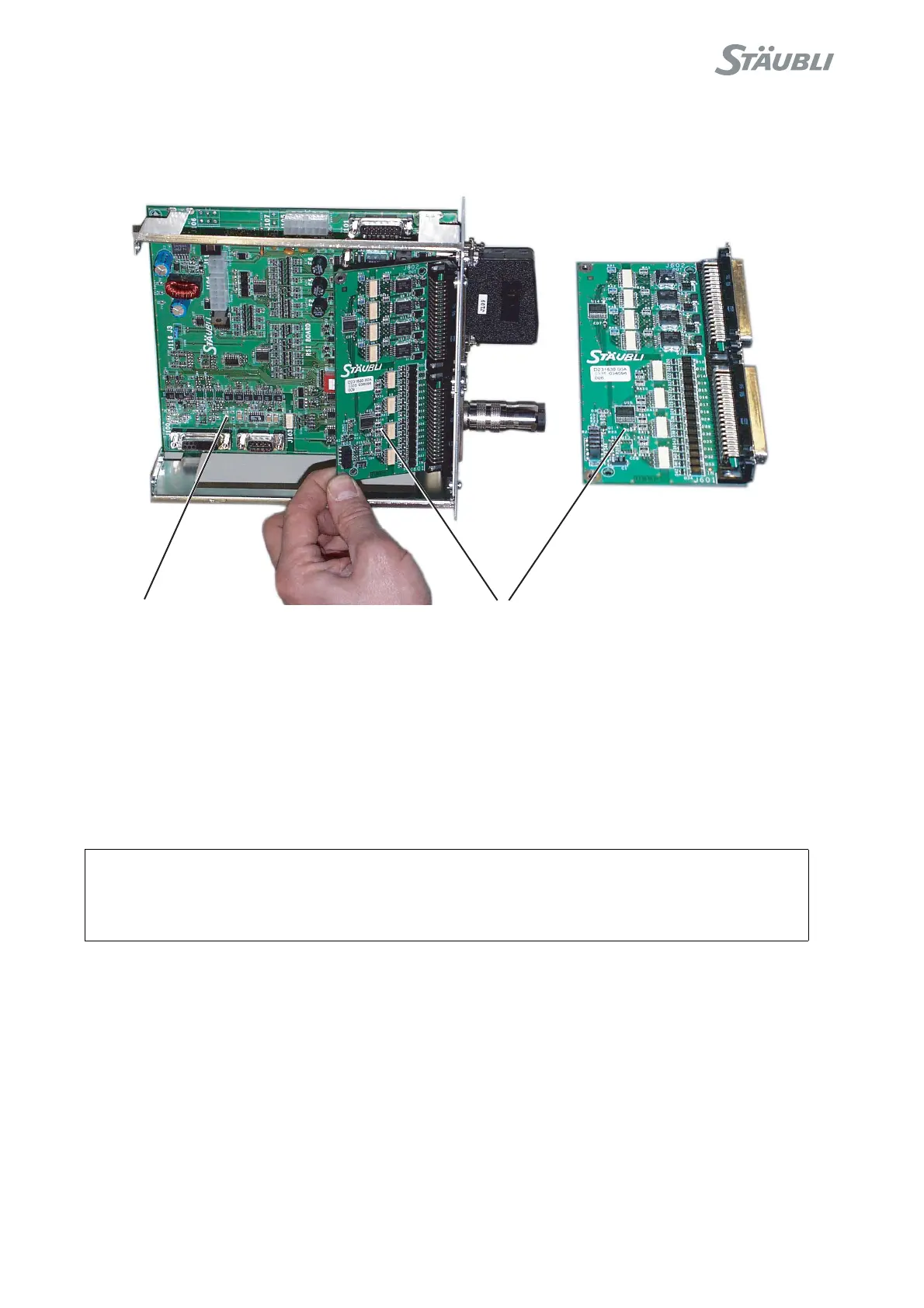
BIO 16I / 16O board description
Figure 5.15
The kit is made up of a BIO board to be mounted on the RSI board. Up to 2 BIO boards can be used.
The BIO board is fitted with:
•16 optocoupler inputs.
The signals are numbered from 0 to 15 on each board and they correspond to inputs 0 to 15 and then 16 to 31.
•16 optocoupler outputs protected against overcurrents.
The signals are numbered from 0 to 15 on each board and they correspond to outputs 0 to 15 and then 16 to 31.
Wiring the I / 0s
Wiring is described in the "Electric Wiring" manual.
CAUTION:
The Inputs/Outputs have to be powered by a rectified, filtered external power source (not
supplied).
RSI
BIO