CS8C © Stäubli 2009 – D28070504A
49 / 248
Chapter 4 - Installation
4.6.3. CONNECTING THE SIGNALS
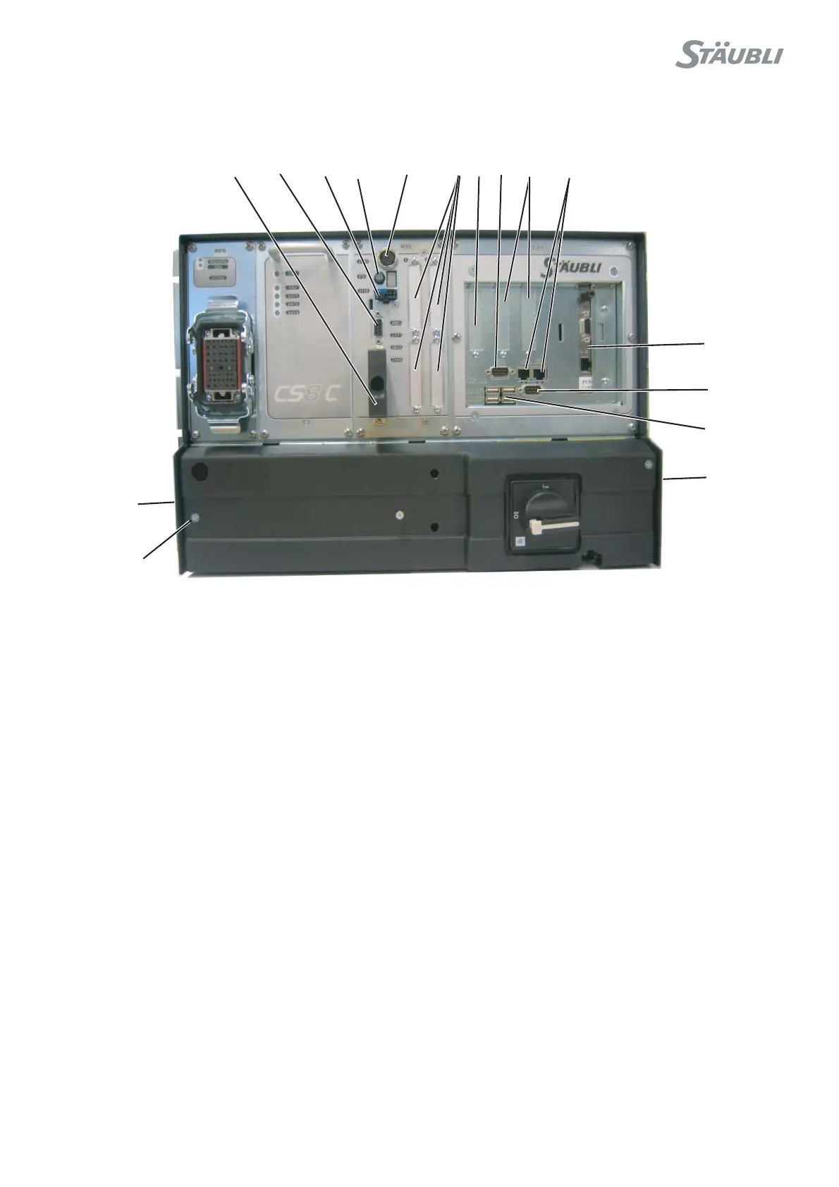
The Input/Output signals are connected via the connectors located on the front panel of the controller.
Figure 4.11
The signals must be connected using shielded cables whose shield is grounded at the both ends. This is
necessary both for the emergency stop signals (J109) and for the digital links (serial links, Ethernet, etc.).If screw
terminal type connectors are preferred, an adaptor from Sub D to screw terminal is commercially available from
several sources such as Phoenix Contact and others.
The brackets used to hold the controller in place also provides protection from electrical noise. It is thus useful for
the fastenings (8) to be linked to the ground circuit of the cell as a whole.
Note:
For RS robots, there are also Inputs/Outputs available on the arm.
2: Connector for MCP
3: Fast Inputs/Outputs
4: Connection with cell (emergency stop, door, etc.)
5: Digital I/O options (BIO)
6: Ethernet links
7: Serial links
9: USB links
10: Anti-static wrist strap
11: Optional encoder input
12: CAN output for Scara robots
13: Connector for WMS front panel
14: Optional fieldbus board
5
4
3
2
7
7
9
10
8
8
6
13
F2
14
12
11