© Stäubli 2009 – D28070504A CS8C72 / 248
5.3.1.2. INSTALLATION OF CABLE
• The cable has to be connected to J211 on CS8C computer module and on J1202 on arm.
5.3.1.3. INSTALLATION OF I/O BOARD IN THE ARM
Remove the 2 side covers and the outer cover of the forearm.
The board has to be attached by screws and connected to XB3 plug on the LPX5 board.
5.3.1.4. SOFTWARE SETUP
5.3.1.5. PROCEDURE FOR CONNECTING THE INPUTS/OUTPUTS IN THE FOREARM
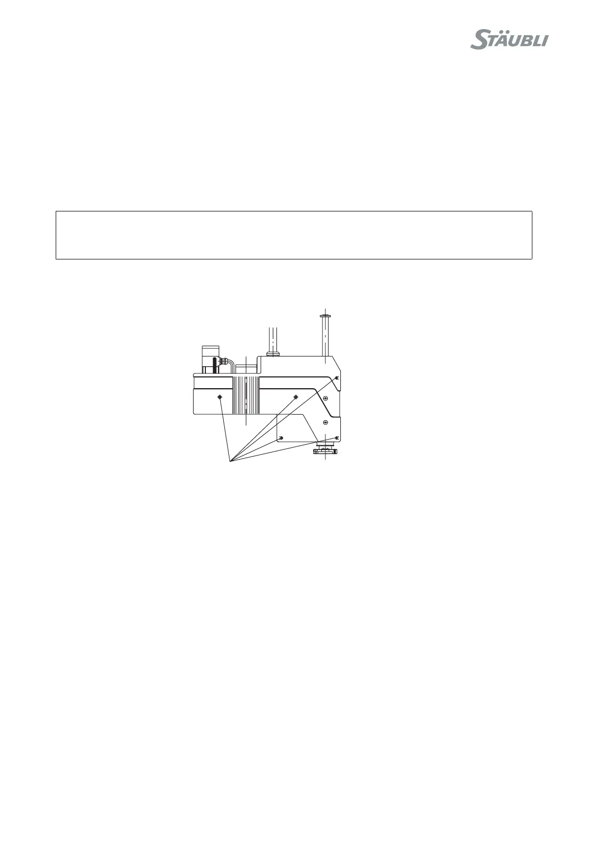
1) Remove the outer cover from the forearm.
2) Loosen the screws holding the cover in place and remove the cover.
3) The user cable comes out of the forearm cover:
• Towards the top by cutting out an opening (d = 23.5 mm) in the cover and inserting a seal (e.g.PG16) in
the opening.
4) Insert the cable through the connection and connect it to the terminals on the CIO/ARMIO board. Fit the
connectors on the CIO/ARMIO board. Group and fasten the cables together (for a cable exit on the side, on
the flat metal surface just below).
Note:
The connectors for the CIO/ARMIO board are included in the pack (constructor Weidmüller,
description 14 pin BL 3.5/14/F, order n° 160 676 0000).
5) Put the cover back in place.
6) Fit the outer cover on the forearm.
CAUTION:
The RS40/60/80 arm must be switched off.
Screws holding the cover on the forearm