CS8C © Stäubli 2009 – D28070504A
203 / 248
Chapter 8 - Maintenance
8.8. RSI
Note:
First CS8C controller generations were equipped with RSI(1) board which changed to RSI2 from
2007. "RSI" applies for both RSI(1) and RSI2 where RSI(1) or RSI2 applies specifically to a
dedicated board version.
8.8.1. DESCRIPTION
RSI board manages all hardware signals for safe operation of the robot.
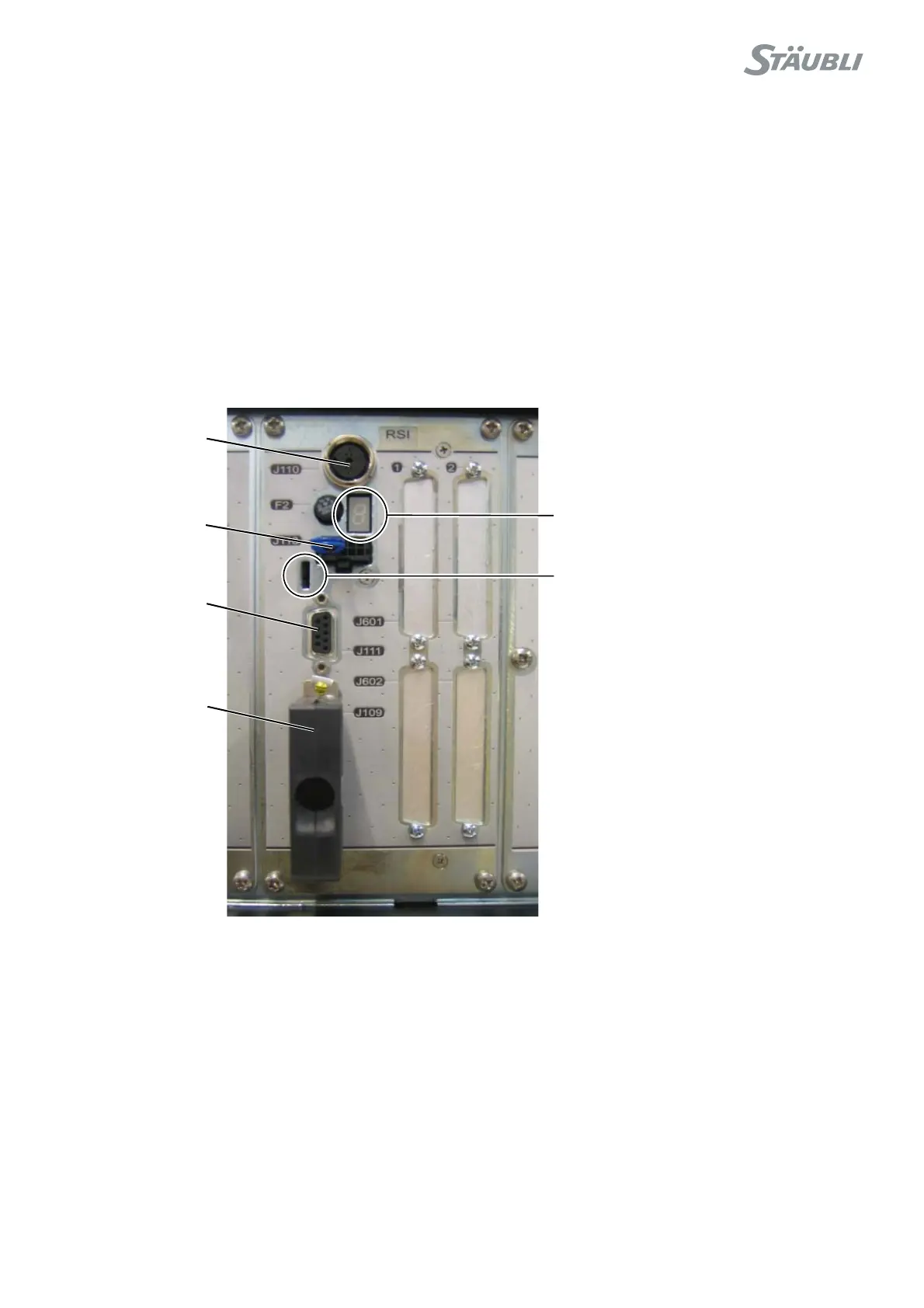
RSI2 board front view:
Figure 8.42
J110
J113
J111
J109
A 7-segment display indicates status of
internal signals. Refer to page 209 for error
codes.
Power status is indicated with green lights:
D49: 24 V power supply
D50: 5V internal power supply
D52: 5V power supply from STARC2
board
D74: Valve 2 through F5 fuse
D73: Valve 1 through F6 fuse
Refer to pages 204 and 208 for trouble
shooting.