© Stäubli 2009 – D28070504A CS8C70 / 248
5.3. RS ROBOTS
In the case of RS robots, Inputs/Outputs are available as an option on the forearm using the CIO board (first
generation) or ARMIO board (second generation):
•8 x 24V digital inputs
•8 x 24V digital outputs
•4 x ±10V analog inputs
•4 x 0/+10V analog outputs (only for ARMIO second generation)
These Inputs/Outputs are driven from the controller via a dedicated CAN bus. The CAN bus is connected to J211
on controller side and J1202 at the base of the arm. A user cable can be supplied as an option to take the intputs
/ outputs as close as possible to the tool flange through the ball screw.
An ASI bus can also be supplied as an option on the CIO board (not available on ARMIO board).
The "Control panel" page allows you to see the status of the CAN Inputs/Outputs.
Note:
To display the status of the Inputs/Outputs or to programme them, select the "I/O" branch in the
control panel accessible via the main menu.
5.3.1. INSTALLATION OF THE OPTION
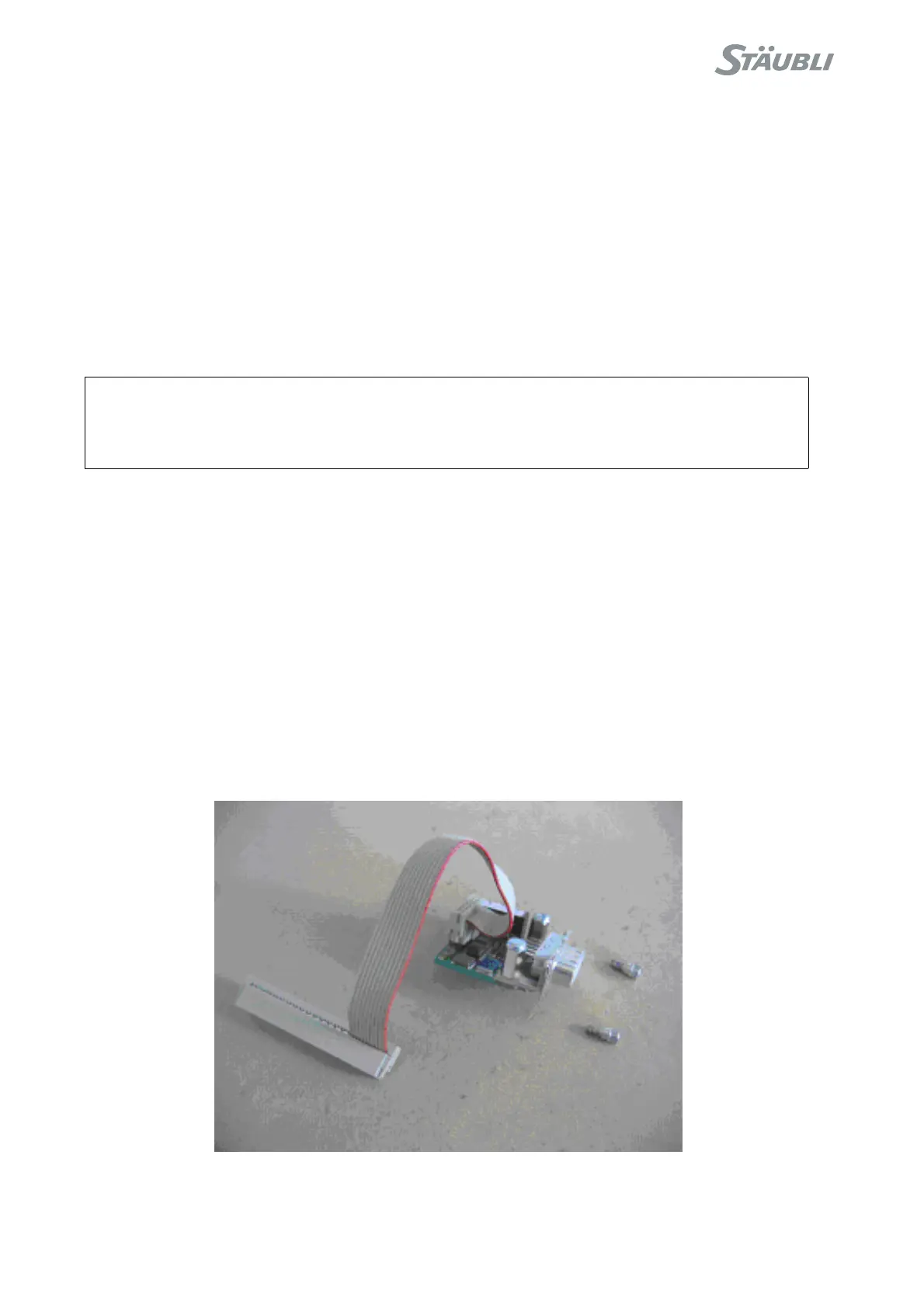
The option includes:
• A CAN board to be installed in the CS8C computer module. The board is provided with a cable and mounting
screws.
• A cable between CS8C and the base of the arm.
• An I/O board for the arm.
Figure 5.10
CAUTION:
If this cable is fitted, rotation of joint 4 must be limited to ±180°. This limitation is configured
at the factory if the option is supplied.