© Stäubli 2009 – D28070504A CS8C76 / 248
Hardware configuration
If the ASI bus is powered via the CIO board, only 4 slaves can be connected.
If an outside power supply is used, 13 slaves can be connected. This power supply must conform to AS-I
specification.
The CIO board has configuration switches whose positions must be as follows:
• 1, 7, 8 = on
• 2, 3, 4, 5, 6 = off (see figure 5.13)
MEANING
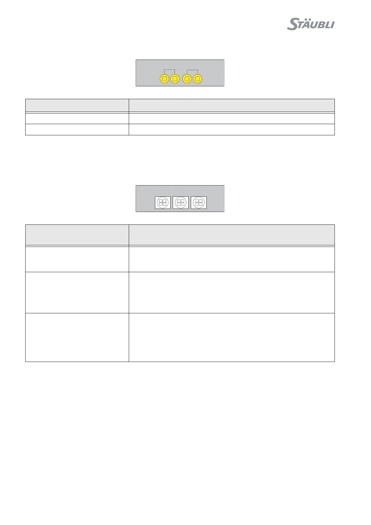
JP1, JP2 present Power supply for the ASI bus provided via the CIO board
JP1, JP2 absent External power supply for the ASI bus
LIGHT EMITTING DIODES
LED DISPLAY
MEANING
LED1
Green
Red
Logic signal OK
Overload
LED2
Green
Flashing green
Red
Steady OFF
ASI data transfer
Waiting for CAN data
ASI voltage error
CIO board without ASI module
LED3
Red
Flashing red
Fast flashing red
Green
Flashing green
CAN bus not operational
ID node not valid
Module in passive error status
Module in operational status
Module in pre-operational status
JP1
JP2
LED1LED2LED3