© Stäubli 2009 – D28070504A CS8C50 / 248
4.6.4. CABLE INLETS AND OUTLETS
The connections for the CS8C controller are on the front panel. They must then be protected by backshells with
good levels of mechanical strength and the cables have to be attached to the frame of the cell to avoid constraints
on connectors.
Note:
Grounded metal backshells provide improved protection from unwanted outside currents.
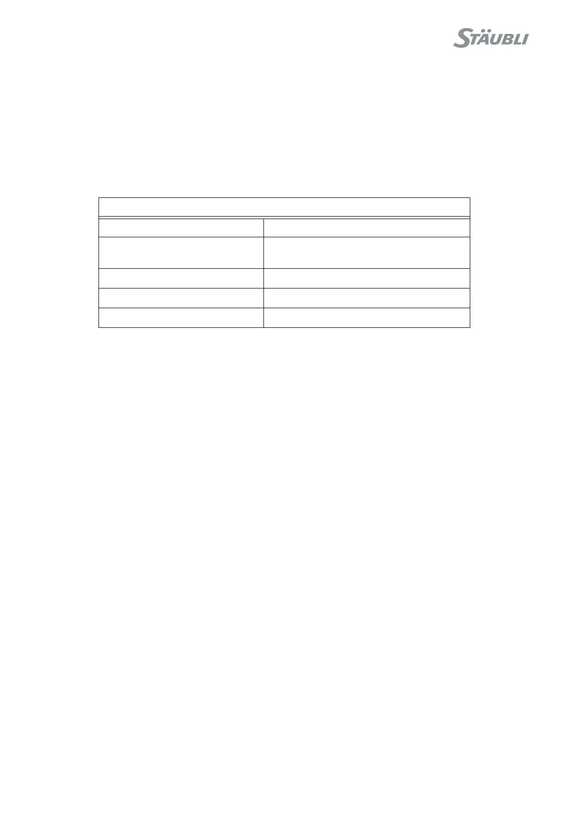
The cable layout must comply with a minimum radius of curvature for each type of cable. See the table below:
Note 1:
During installation, the ends of the interconnection cable should be covered to protect them from
dust. The only cleaning product that can be used is water. Never use alcohol.
Note 2:
Flat interconnection cable requires more space on controller side. The flat cable has to be
installed in a chain to guaranty a good operation and dynamic constraints have to be applied to
the cable itself, not the connectors.
Flat cable characteristics:
• Minimum dynamic bend radius: 110
• Max speed: 4 m/s
• Max accel: 8 m/s²
• 5.000.000 cycles maximum
Minimum radius of curvature in mm
Standard interconnection cable 100
Flat interconnection cable static bend radius: 55
dynamic bend radius: 110
hand I / O cable 50
MCP and WMS cables 50
Other Depending on the cables used