CS8C © Stäubli 2009 – D28070504A
61 / 248
Chapter 5 - Integration
5.1.2. CONNECTION WITH CELL
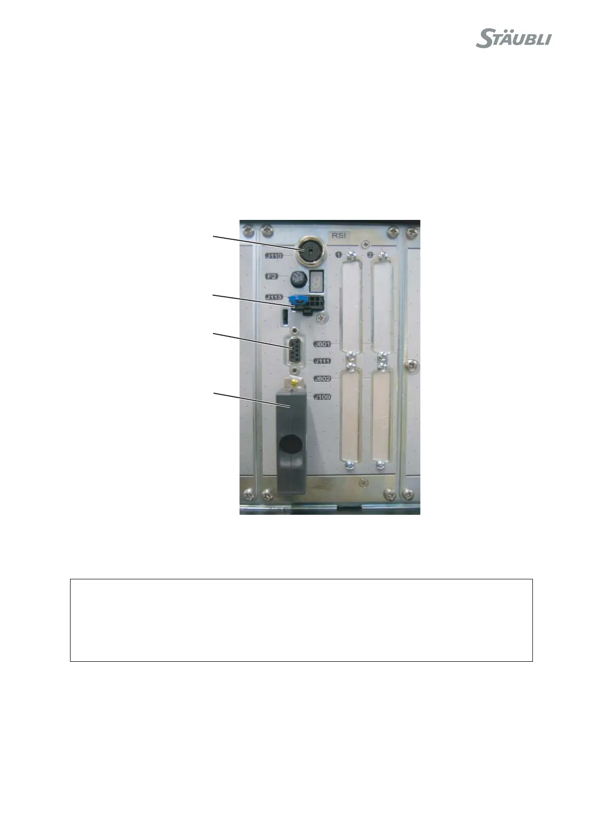
Description of connection point
The RSI board is connected to the equipment in the cell via the J109 connector on the board on the front panel of
the CS8C controller.
All the contacts to be connected up in the emergency stop channels must be duplicated dry contacts. An
emergency stop button must activate two contacts at the same time, and the maximum authorized time lapse
between the opening of the two contacts is 100 ms. If this time lapse is exceeded, an error message is displayed.
All the information supplied by the RSI board are in the form of dry contacts.
Figure 5.5
Note:
If screw terminal type connectors are preferred, an adaptor from Sub D to screw terminal is
commercially available from several sources such as Phoenix Contact and others.
CAUTION:
The CS8C controller is supplied with a "shorting connector" for J109 that can be used to
power up the robot without wiring up the emergency stops. This connector is provided for
diagnosis purposes only. It must be replaced by suitable wiring on the emergency stop
circuits.
J110
J113
J111
J109