Disassembly Diagram
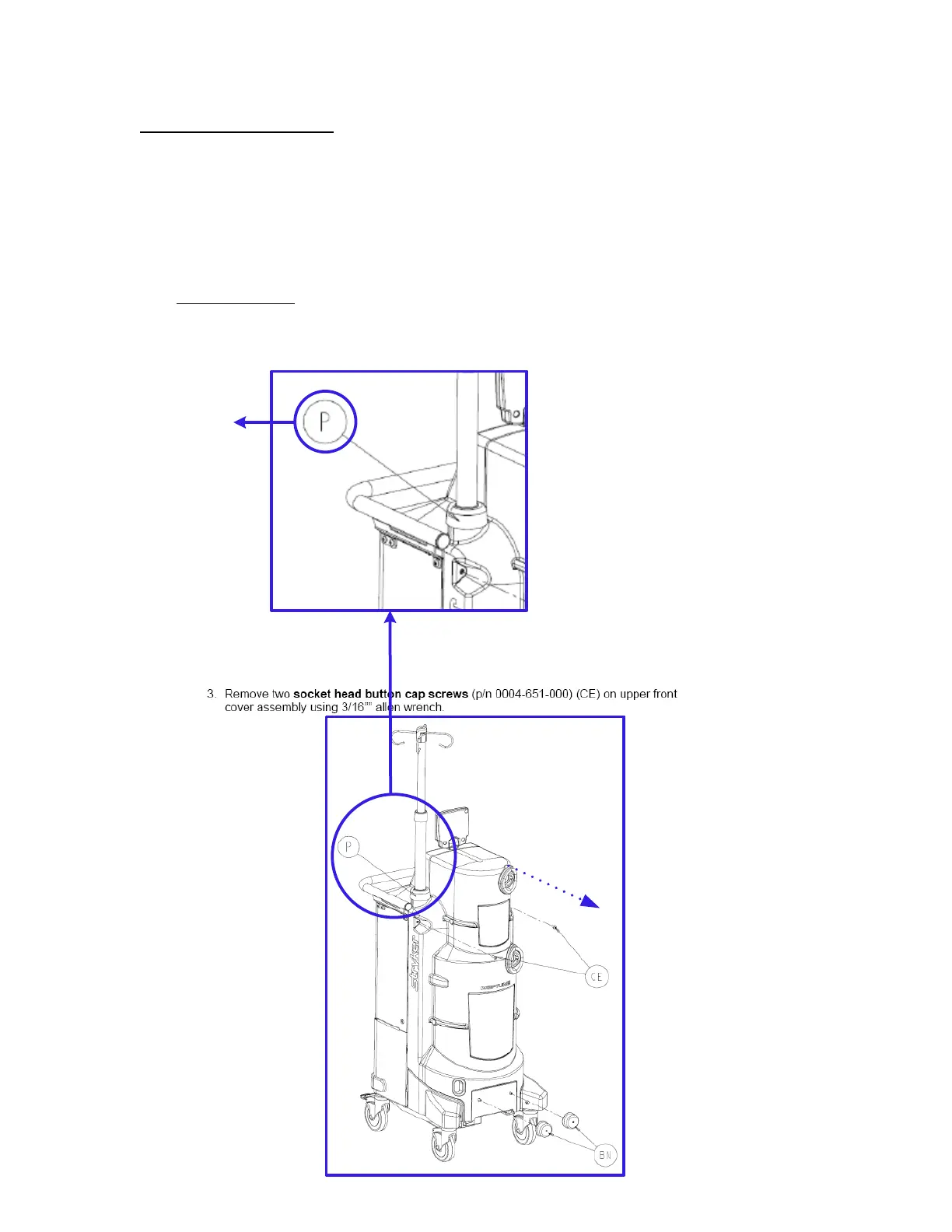
The diagram provides the technician with a visual reference of the components to be
removed. The reference designators shown help the technician to correspond each part in the
diagram to the one listed in the disassembly step. Dashed lines indicate a motion path for parts
to be removed. It is important to understand that any parts mentioned in the removal step will
be shown in bold, immediately followed by the part number and reference designator.
However, only the part being removed in each step will have a corresponding reference
designator in the diagram. This allows the technician to clearly indentify which part is being
removed while also still providing the part number information for all parts in the Neptune
system.
DISASSEMBLY
DIAGRAM
Indicates a
removal path
for components
Reference
designator
vi

 Loading...


