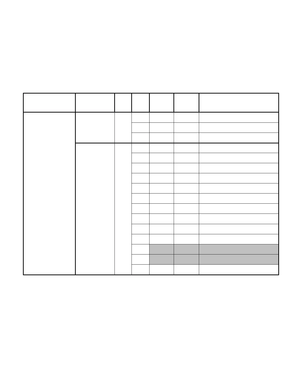
System Troubleshooting Chart
Main Control Board
Component
Measurement
Location
Black
Lead
Red
Lead
Reading
Unit of
Measure
State
Main Control Board
J7 on Board Pin 7
Pin 1 20 VDC Rover power on, system idle
Pin 2 5 VDC Rover power on, system idle
Pin 3 3.3 VDC Rover power on, system idle
J8 on Board Pin 1
Pin 2 3.3 VDC Rover power on, system idle
Pin 3 3.3 VDC Rover power on, system idle
Pin 4 3.3 VDC Rover power on, system idle
Pin 5 3.3 VDC Rover power on, system idle
Pin 6 3.3 VDC Rover power on, system idle
Pin 7 3.3 VDC Rover power on, system idle
Pin 8 3.3 VDC Rover power on, system idle
Pin 9 3.3 VDC Rover power on, system idle
Pin 10 3.3 VDC Rover power on, system idle
Pin 11 3.3 VDC Rover power on, system idle
Pin 12 n/a n/a n/a
Pin 13 n/a n/a n/a
Pin 14 5 VDC Rover power on, system idle
5-9

 Loading...


