Rover System Block Diagrams – Ultra Rover
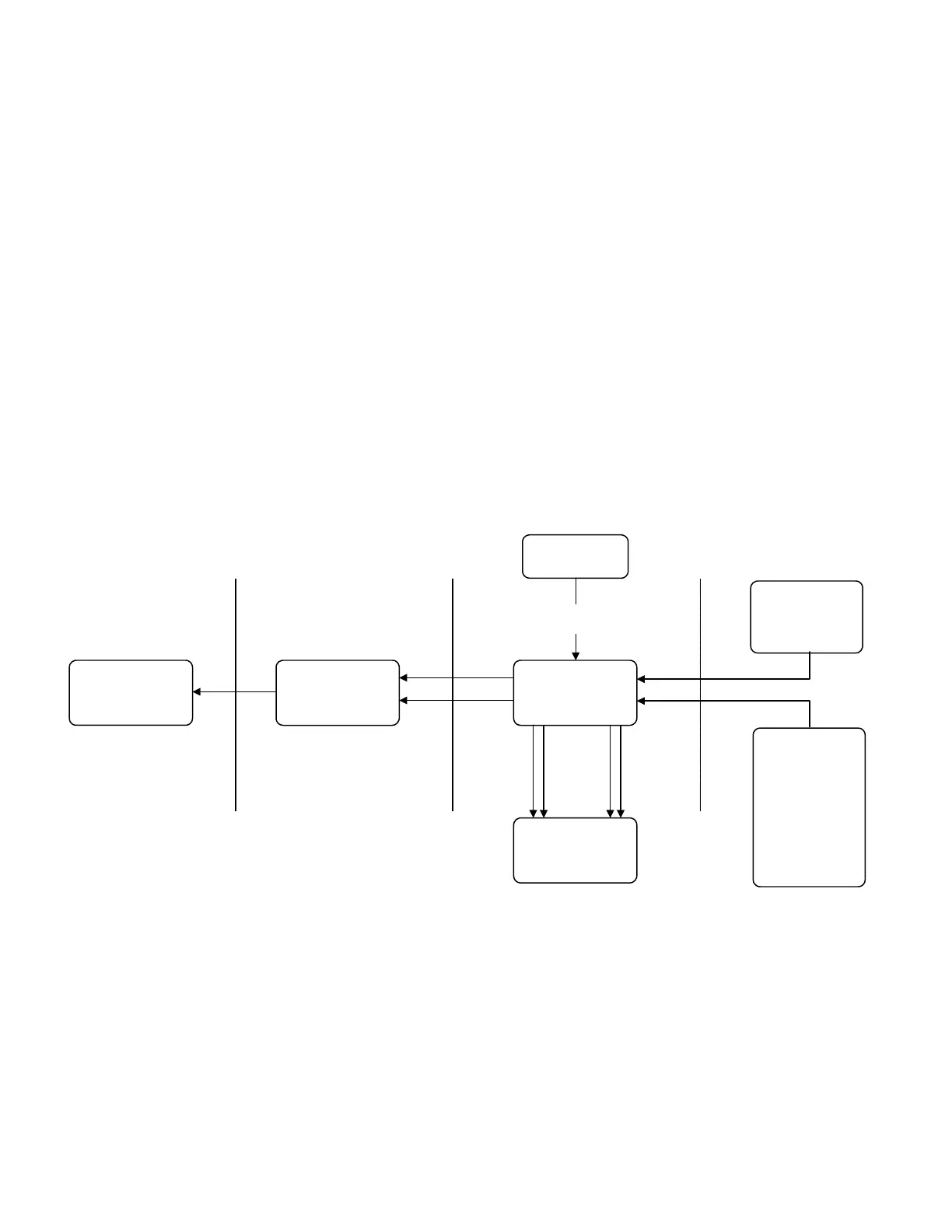
Vacuum System
Although the vacuum pump is the source, it is drawing air in rather than
exhausting. Just as in the troubleshooting example, a bad check at any point still
requires a move towards the source. The technician should not confuse
troubleshooting the vacuum pump with standard troubleshooting simply because it does
not have an output. Checks are made the same way as with the rest of the system. The
vacuum system block diagram is drawn with arrows pointing towards the vacuum pump
to illustrate the air flow in the system, while the arrows going to the power control board
represent a sample of the suction level going to the board. If suction is not present at a
half-split point, the technician should check a point closer to the vacuum pump to
determine where the failure lies.
Vacuum Pump
HEPA Filter
Housing
Vacuum Manifold
Assembly
Power Distribution
Board
Vacuum
Sensor
Lines
Small
Canister
Large
Canister
UIP
Suction
Control
5-5

 Loading...


