Home
Stryker
Medical Equipment
Neptune 2
Stryker Neptune 2 Service And Installation Manual
4
of 1
of 1 rating
232 pages
Give review
Manual
Specs
To Next Page
To Next Page
To Previous Page
To Previous Page
Loading...
Injector Pump Assembly P/N 0702-001-380
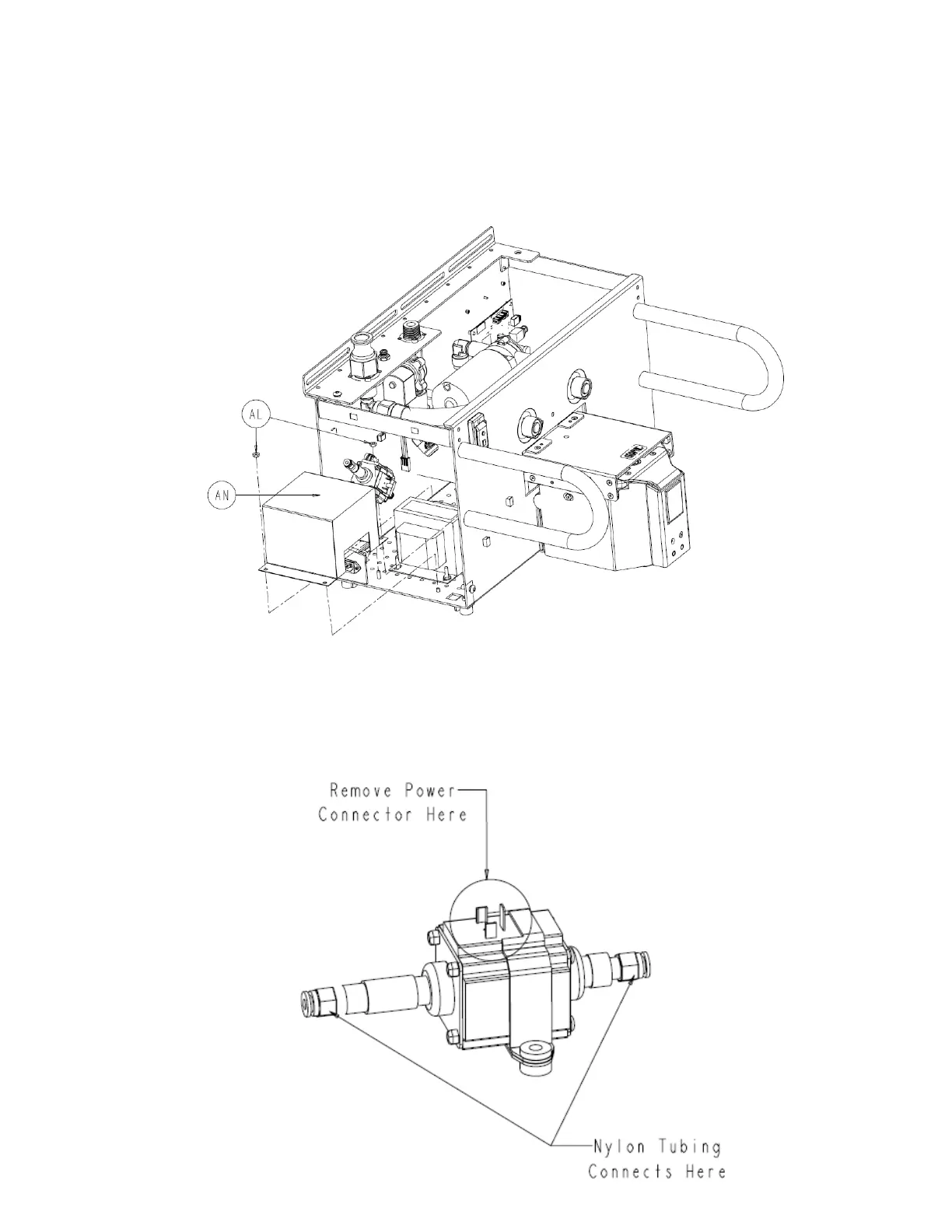
1. Remove
two
hex nuts
(P/N 0015-004-000) (AL).
2. Remove
transformer cover
(P/N 0702-014-025) (AN) and set aside.
3.
Using a #2 phillips screwdriv
er, unscrew the fastener holding
the power connector to the
injector pump assembly
(P/N 0702-001-380) (AJ) and
pull connector off.
4-15
121
123
Table of Contents
Default Chapter
6
Docker Disassembly
6
Operational Description
6
Solo Rover Disassembly
6
Ultra Rover Disassembly
6
Disassembly Basics
7
Warning Indicators
7
Warning Indicators and Disassembly Procedure Example
7
Assembly Title
8
Disassembly Diagram
8
Front Panel Assembly
9
Disassembly Step
10
Docking Station Block Diagrams
12
Troubleshooting
12
Troubleshooting Overview
12
Ultra Rover Block Diagrams
12
Neptune Error Codes
13
System Setting Menu
13
System Troubleshooting Chart
13
Technician Menu Overview
13
Installation
14
Technical Procedures
14
Table of Contents
16
Chapter 1 - Operational Description
22
General Description
24
Small Canister
24
Large Canister
24
Vacuum
24
Pre-Fill
25
Smoke Evacuator
25
Docking Mechanism
25
Docking Functions
25
IV Pole
25
User Interface
26
Chapter 2 - Ultra Rover Disassembly
28
Front Panel Assembly P/N 0702-001-070
30
Remove Front Cover Assembly
31
Rear Panel Assembly P/N 0702-001-060
33
Lower Panel Assembly P/N 0702-001-030
34
Bumper Assembly P/N 0702-001-940; 0702-001-950
35
Top Cover Assembly P/N 0702-001-090
36
Main Control PCBA P/N 0702-001-800
41
Volume Display Assembly P/N 0702-001-840
48
Removing Large and Small Canisters P/N 0702-001-320 & 0702-001-300
54
Separation of Large & Small Canister Assemblies
60
Small Canister Assembly P/N 0702-001-300
64
Power Transformer Assembly P/N 0702-001-830
68
Coupling Block Assembly P/N 0702-001-600
69
Exhaust Plenum Assembly P/N 702-901-930
71
IV Pole Assembly P/N 0702-001-500
73
Prefill Tank P/N 702-007-370
75
Prefill Pump Assembly 0702-001-380
76
Fluid Diverter Assembly P/N 0702-001-350
77
Smoke Evacuator Assembly Removal P/N 0702-001-400
80
Vacuum Manifold Assembly P/N 0702-001-110
85
Fluid Suction HEPA Housing Assembly P/N 0702-001-110
88
Vacuum Pump Assembly P/N 0702-001-100
90
Silencer Manifold Assembly P/N 0702-001-160
93
Caster Assembly P/N 0702-001-012; 0702-001-013
94
Manifold Receptacle Assembly P/N 0702-001-230
95
Rover Power Coupler Circuit Board Assembly P/N 0702-001-086
96
Power Entry Module P/N 0702-001-862
97
Canister Door Removal P/N 0702-001-070P; 0702-001-070R
98
Power Distribution PCBA P/N 0702-001-035
99
AC Power PCBA P/N 0702-001-802
101
Chapter 3 - solo Rover Disassembly
104
Chapter 4 - Docker Disassembly
106
Chassis Top Cover Removal P/N 0702-014-011
108
Actuator Assembly P/N 0702-014-100
109
Docker Power Coupler Assembly P/N 0702-014-114
113
Extend Hall Sensor P/N 0702-014-119
115
Hall Sensor P/N 0702-014-906
115
Stepper Motor P/N 0702-014-123
117
Offload Pump P/N 0702-014-201
119
Electromagnet P/N 0702-014-920
121
Injector Pump Assembly P/N 0702-001-380
122
Docker Isolation Transformer P/N 0702-014-520
124
Water Inlet Assembly P/N 0702-014-400
126
Docker Power Coupler PCBA P/N 0702-014-510
127
Docker Main Controller PCBA P/N 0702-014-500
128
Power Switch P/N 0700-001-412
130
Power Plug Module P/N 0702-014-019
132
Chapter 5 - Troubleshooting
134
IV Pole Normal Operation
136
Troubleshooting Overview
136
Bracket Moves Left Towards the Signal’s Source
137
Verify Input from Membrane Switch
138
Main Control Board Not Operating Correctly
139
Main Control Board Operating Correctly
139
Rover System Block Diagrams – Ultra Rover
140
Vacuum System
140
Fresh Water System
141
Waste System
142
Docking Station Block Diagram
143
Main Control Board
144
System Troubleshooting Chart
144
AC Power Board, Volume Display Board, & Tank Valve Motor
146
Pole, Fluid Diverter, Power Coupler, Prefill Pump, & Canister Calibration Board
147
Adjusting System Settings
148
System Settings Menu Overview
148
To Access System Setup
148
Neptune Splash Screen
149
Sample System Setting Screen
149
System Setup Screen
149
System Setting Options
150
Technician Menu Overview
151
To Access the Technician Menu
151
Docking
152
Technician Menu Options
153
Neptune Error Messages
156
Technician Menu
152
Neptune 2 Error Codes
156
Chapter 6 - Technical Procedures
168
Accessing Menu While Docked
170
Procedure 6.1 - Priming the Detergent Pump
170
Technical Procedures Overview
170
Accessing the Technician Menu
171
Select DOCKING Option
172
Select the DOCKING Option
172
Procedure 6.2 - Manually Filling the Detergent Tube
174
Determining Which Reprogram Option to Use
175
Procedure 6.3 - Reprogramming Rover Software
175
Access the Technician Menu
176
Select the REPROGRAMMING Menu
176
Reset Eeprom
177
Select the Desired Option
177
Reprogram Main
178
Reprogram Pd
178
RESET EEPROM Confirmation Screen
178
Upgrade Software Screen
178
Procedure 6.4 - Performing the Canister Calibration
179
Empty the Fluid Collection Canister
182
Amp Draw Test (Covers Removed)
188
Neptune Rover Testing Requirements
188
Procedure 6.5 - Testing
188
Wire Integrity Test (Covers Removed)
188
Analyzer Settings and Earth Leakage Current Limit for Rover
189
Earth Leakage Current Test (Covers Removed)
189
Patient Leakage (Covers Removed)
189
Analyzer Settings and Patient Leakage Current Limit for Rover
190
Hi-Pot Settings for Rover
191
Hi-Pot Test (Covers Installed)
191
Ground (Earth) Resistance Test (Covers Installed)
192
IV Pole
193
Rover Functional Test
193
Smoke Evacuator Function
193
Vacuum Function
193
Functional Test / Amp Draw Test (Covers Removed)
194
Neptune Docker Testing Requirements (P/N 0702-014-000)
194
Hi-Pot Settings for Docking Station
195
Earth Leakage Current Test (Covers Installed)
196
Procedure 6.6 - Clearing a Clog in the Small Canister
198
Turn on Main Power Switch
202
Procedure 6.7 - Finding a Missing Magnet
204
Transducer Rod and Magnets
204
Level Sensor Data
205
Response Time Values for Level Sensor
205
Expected Value Range for Magnets
206
Hexadecimal to Decimal Conversion
206
Magnet Failed
206
Data Screen Displays Zeros for a Missing Magnet
207
Level Sensor Data Screen; All Magnets Functioning Normally
207
Hold Upper Right Hand Button
210
Procedure 6.8 - Manually Raising & Lowering Docker Couplers
212
Neptune Rover (P/N 0702-001-000)
216
Procedure 6.9 - Preventive Maintenance
216
Neptune Docking Station (P/N 0702-014-000)
217
Procedure 6.10 - Cleaning the Fluid Collection Canisters
218
Chapter 7 - Installation
220
Description
222
Important Information
222
Indications for Use
222
User/Patient Safety
222
Docking Station Feature Locations
223
Features
223
Minimum Space Requirements
223
Docking Station Installation
224
Symbol Definitions
224
Cleaning Recommendations
225
Periodic Maintenance
225
Storage and Handling
225
To Install the Docker
225
Problem Cause Action
226
Troubleshooting Guide
226
Environmental Conditions
227
Chapter 8 - Appendices
228
Infrared Communication Windows
227
Protective Earth Ground
227
Specifications
227
Appendix A - List of Materials
230
Appendix B - Power Distribution Block Diagram
232
Other manuals for Stryker Neptune 2
Installation, Operation And Maintenance Guide
24 pages
Instructions For Use
13 pages
4
Based on 1 rating
Ask a question
Give review
Questions and Answers:
Need help?
Do you have a question about the Stryker Neptune 2 and is the answer not in the manual?
Ask a question
Stryker Neptune 2 Specifications
General
Brand
Stryker
Model
Neptune 2
Category
Medical Equipment
Language
English
Related product manuals
Stryker Neptune S
78 pages
Stryker Power-PRO 2
76 pages
Stryker Crossfire 2
66 pages
Stryker CORE 2 Console
12 pages
Stryker Nara
28 pages
Stryker T2
44 pages
Stryker 1115
84 pages
Stryker Visum
44 pages
Stryker LUCAS 3
3 pages
Stryker InTouch
34 pages
Stryker T/Pump Series
54 pages
Stryker ProCuity Series
56 pages