For the most part the process starts with the covers and proceeds through
removing each component, one at a time. The technician should ensure that the
equipment is unplugged and turned off during disassembly!! Power should not be
applied when removing components or subassemblies. Components are assembled in
reverse order of assembly and therefore reassembly of the equipment is not covered.
Disassembly Diagram
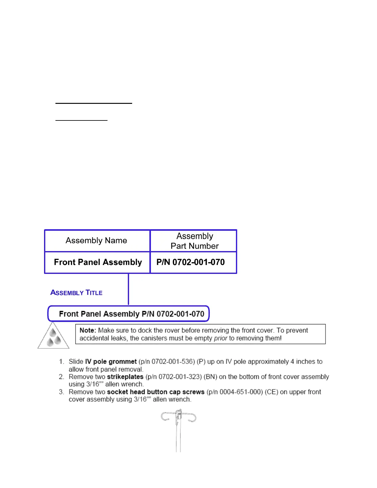
Assembly Title
The assembly title consists of the name and the part number of the component to
be removed. If an assembly has additional parts that can be removed, the technician
should refer to the procedure for that part. For example, page 2-7 outlines the steps to
remove the top cover assembly. There are also removal procedures for two
components on the top cover assembly. (These are the main control board on page 2-
12 and the volume display assembly on page 2-19) Each of the two subassemblies of
the top cover begins with taking off the top cover. Always verify that the procedure being
followed is for the part you intend to replace. The number of steps involved and the
order they are performed may vary depending on which part is being replaced.
iii

 Loading...


