Procedure 6.5 – Testing
The testing listed in this section is performed after every service call, whether the
maintenance action is a repair or scheduled preventive maintenance. The testing includes both
electrical testing as well as a functional check. The rover and docker testing is completed in
two stages. They are first tested with the covers removed, and then the tests are completed
once the covers have been reinstalled. The test equipment used in the following procedures is
listed in Appendix A. The list is only a reference designed to aid the technician in choosing
suitable test equipment. The exact model is not required, but a suitable equivalent must be
used when performing safety testing.
For example, the safety analyzer must be able to check earth leakage current in
reversed polarity, but it does not have to be the Dale Technologies model listed in Appendix A.
In either case, the technician must ensure that the test equipment used is within the calibration
period, or “In Calibration”, and that any test equipment used has not exceeded the calibration
due date listed. Similarly, if a piece of test equipment does not have a calibration sticker, it can
not be assumed that it is working properly. The technician should attempt to find an alternate
means of testing the Neptune Waste Management System.
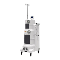
Neptune Rover Testing Requirements (P/N 0702-001-000)
Wire Integrity Test (Covers Removed)
1. Ensure mains wiring (blue and brown wires) inside the chassis are secure and not
touching any components on the circuit boards.
2. Verify wires are secured in a manner to prevent chafing.
Amp Draw Test (Covers Removed)
1. Plug the rover into the safety analyzer.
2. Turn on both the Smoke Evacuator and Vacuum Control (for the small and large
canister) and set both to maximum. (Canister suction and smoke evacuator to 100%)
NOTE: To ensures that the measurement is taken with all functions at maximum, the
technician will need to measure and record the values in step 5 - while performing step 4.
3. Turn the analyzer dial to the INSTRUMENT CURRENT position.
4. Extend the IV pole by pressing the IV pole up button. (Hold through step 5)
5. Measure and record the amp draw. It must not exceed 13.2 amps.
6-19
 Loading...


