Vacuum Manifold Assembly P/N 0702-001-110
Note: Observe how the four norprene sensor lines are routed behind the board block. When
reinstalling the vacuum manifold assembly, make sure to properly place the sensor lines
behind the block to avoid pinching a sensor line.
1. Remove the four norprene tubes (two white and two black) from the power distribution
PCBA (P/N 0702-001-035) (J) that are coming from the vacuum manifold assembly
(P/N 0702-001-110) (N). The motor, power connector, and tubing are specific to the
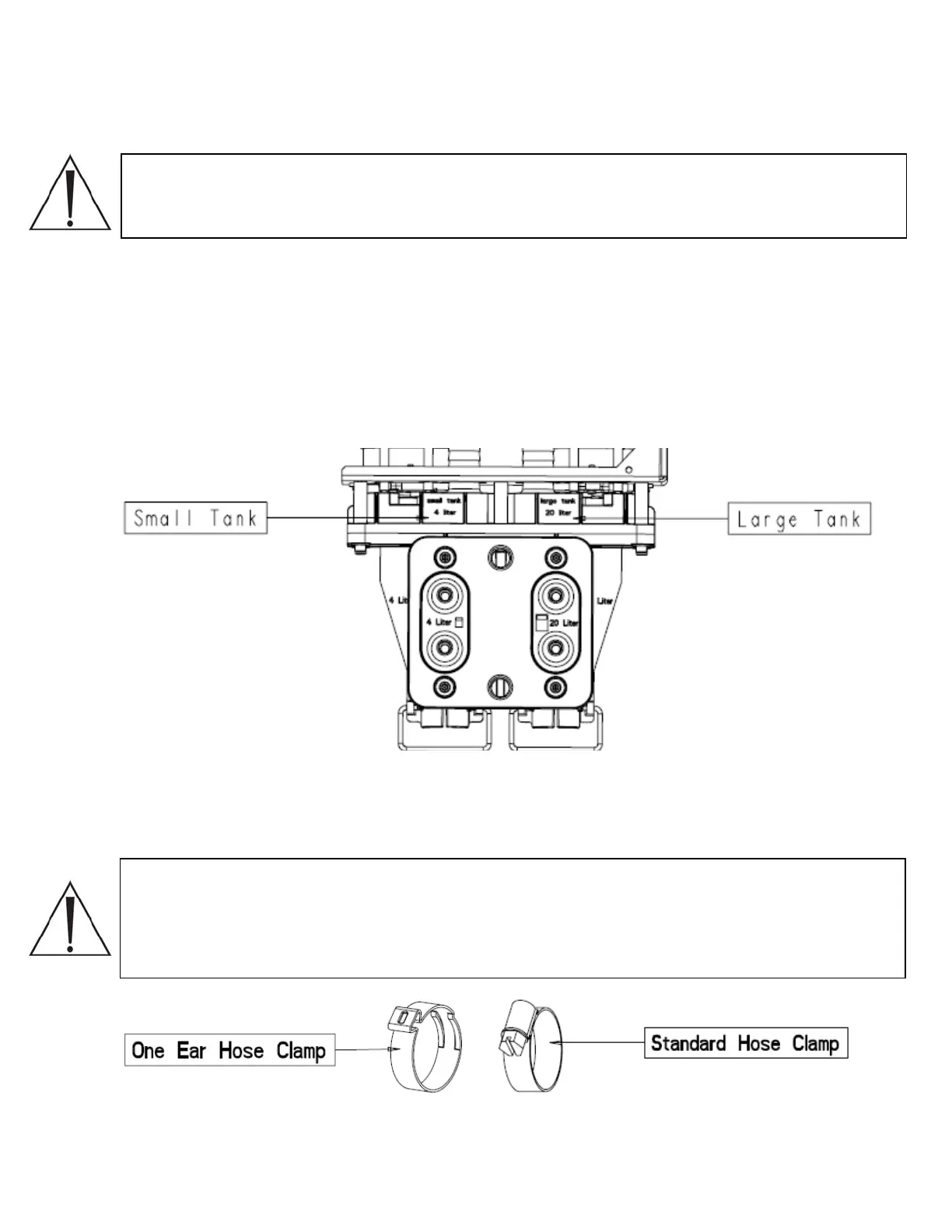
large or small tank. When removing components for each system, note that the
regulators are labeled small tank 4 liter and large tank 20 liter to distinguish the two
controlling subsystems.
2. Disconnect the two power connectors labeled small can regulator and large can
regulator from each of the encoder motors.
Note: There are two clamps on the canister vacuum hose assembly (P/N 0702-001-127)
(CB). One style is a hose clamp (P/N 0058-328-000) (CK), while the other is a one ear
hose clamp (P/N 0058-098-000) (CC). The one ear hose clamp is used during assembly.
The traditional hose clamp should be used once the one ear clamp is removed. The two
clamps are depicted below.
2-56

 Loading...


