Features
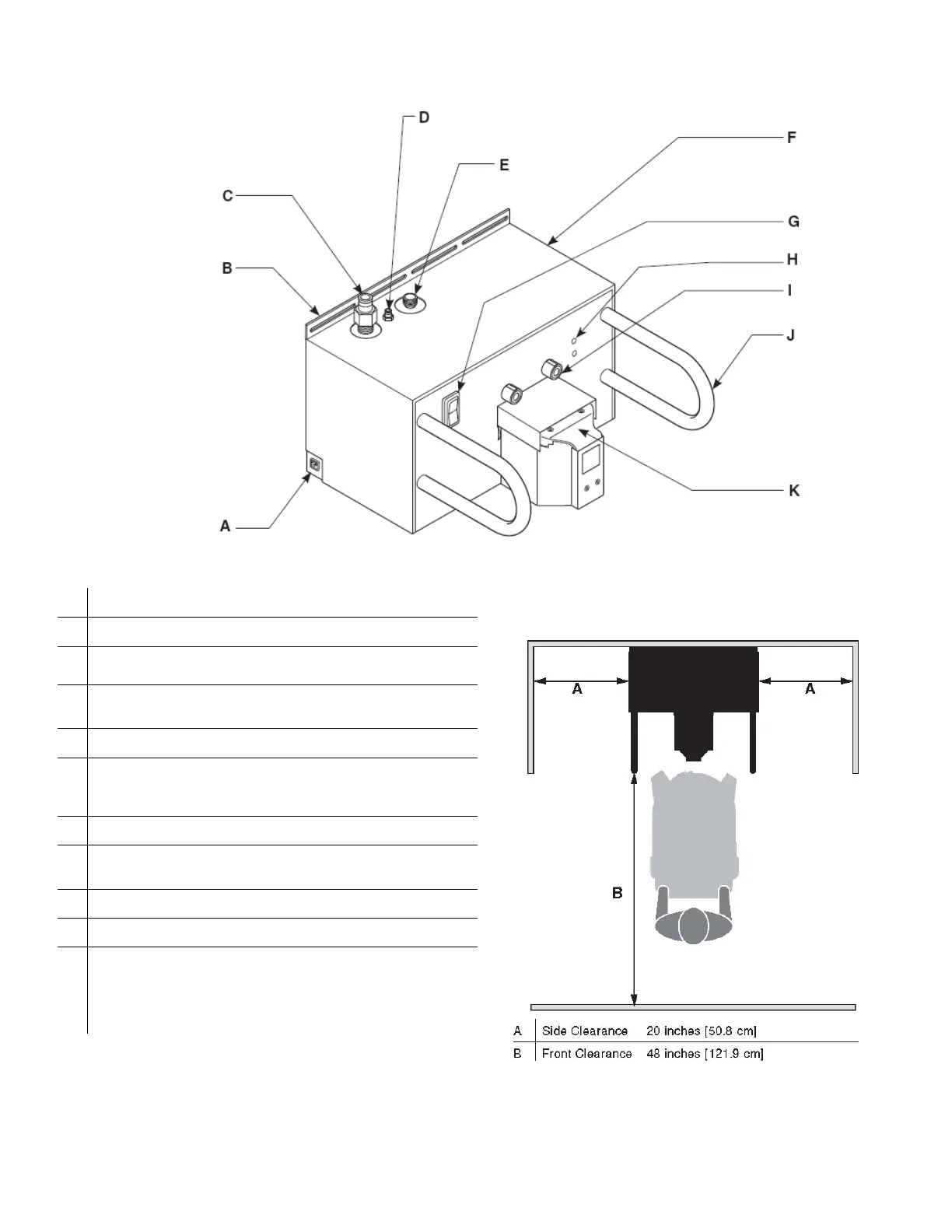
Figure 1: Docking Station Feature Locations
A
Power Cord Receptacle - Allows for the connection of facility
power using the docker power cord.
B
Mounting Bracket - Using mounting hardware, the bracket allows
for the permanent installation of the docker to a flat wall surface.
C
Waste Outlet Port - Allows for the disposal of fluid waste from the
rover when the rover is connected to the docker.
D
Detergent Inlet Port - Allows detergent to enter the rover’s
fluid collection system to facilitate cleaning when the rover is
connected to the docker.
E
Water Inlet Port - Allows fresh water to enter the rover when the
rover is connected to the docker.
F
Ethernet and USB Ports - These ports are located on the side
panel (not visible in illustration) and may be accessed by removing
a cover. Allows for Stryker-approved software upgrades and
maintenance.
G
Power Switch - The toggle switch allows for the application or
removal of facility power.
H
Infrared Communication Windows (two) - Allows infrared data
transfer between the docker and rover. Data transfer is necessary
during the docking procedure.
I
Magnets (two) - Provides for the automatic physical alignment and
connection of the rover to the docker.
J Guides (two) - Facilitates the alignment of the rover to the docker.
K
Power and Fluid Connectors - When the rover is connected to the
docker, the rover receives power through a power connector from
the docker. Two fluid connectors are also present. One connector
allows fresh water to enter the rover. The other connector provides
for the disposal of waste water from the rover. The fluid connectors
are located under a spring-loaded cover.
NOTE: See the Specifications section for electrical power, water, and
drainage requirements. See figures 1 and 2 to ensure the installation
area meets utility and space requirements.
Figure 2: Minimum Space Requirements
7-2

 Loading...


