The point in the circuitry that was found faulty now becomes the right portion of
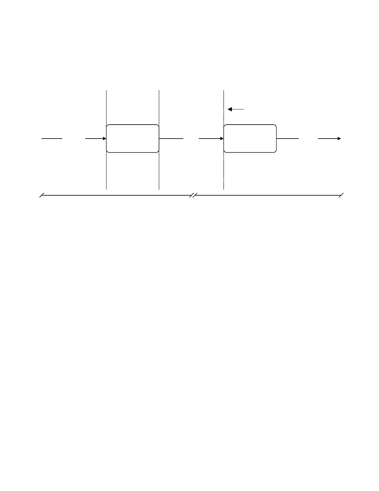
the half split. Figure 2 shows how the bracket is moved left (towards the source) for our
next troubleshooting check.
Power Distribution
Board
Control
From UIP
12 vdc
Input Device Output
IV Pole
IV Pole
Extends
2nd Check : Verify output from power distribution board 1st Check : IV Pole does not work, No 12v Input
Previous Check
Figure 2: Bracket Moves Left Towards the Signal’s Source
In the first check we determined that the motor did not run because of the
missing 12 volt input. Moving towards the source, our bracket now encompasses the
control input from the user interface panel, the power distribution board, and the 12 volt
output to the IV pole motor.
The inputs and outputs to the power distribution board are difficult to check due
to the physical orientation of the board. The circuit board plugs into a backplane with
several connectors. For this reason, the technician will not be able to check the output
of the power distribution board while it is plugged in. The 12 volt input was not present
at the IV pole connector, which leaves the power distribution board via J13, pins 13 and
14. However, we can not assume that the power distribution board is bad without
making a few more checks.
Although we can not check the output of the power distribution board directly, we
can check the interface between the board and the IV pole connector – the wire
harness. This is accomplished by turning off the rover, removing the power distribution
board, and ohming the pins on the backplane connector to the pins on the IV pole
connector. This check will determine if the interface is intact. If any of the pins are open,
then the problem has been discovered and the repair can be completed on the faulty
connector. If all of the pins on the connector ohm correctly then we can assume the
interface is good and proceed to the left (towards the source) for the next check.
5-2
 Loading...


