viii
System Troubleshooting Chart
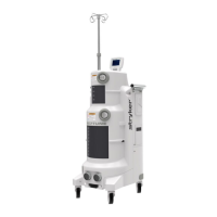
This section provides data for each subsystem in the Ultra rover. Proper
troubleshooting requires the technician to be able to determine whether the equipment
is performing as it should. The chart provides voltage and resistance measurements for
the subassemblies in the rover. This should enable the technician to check the
resistance between points to verify continuity, measure for the correct voltage at a
connector, and ultimately to check for proper operation at each subassembly.
System Setting Menu
The system settings menu lists what options the user can change, and explains
how to access those options. This information is also provided to the user in the
Instructions for Use.
Technician Menu Overview
The technician menu is provided exclusively to the technician. Here the
technician will find information on how to manually control the docking sequence,
perform calibrations, reprogram software, and more. It is important to note that the
information listed here is meant for a Stryker certified trained technician only.
This information should be considered sensitive material. It is possible for someone to
adversely affect the operation of the Neptune Waste Management System if they are
unaware. The technician should understand how their menu choices in the technician
menu will affect the system.
Neptune Error Codes
The error messages in the Neptune Waste Management System are categorized
into 17 different groups. Each category relates to a specific subsystem in either the
rover or the docker. Messages are displayed on the suction display on the rover user
interface panel and can be identified by a specific number. Each error code is generated
for a specific failure.
This should aid the technician in narrowing the search for a faulty component or
assembly. In some cases, a fault will generate multiple error codes. For instance, if a
wire harness fails, it may prevent a circuit board from communicating with several
subassemblies. This would result in multiple communication errors. This section
describes what each fault means, what components could generate that fault, and what
the initial troubleshooting steps should be.
 Loading...


