Rover Power Coupler Circuit Board Assembly P/N 0702-001-086
Note: There are two cables labeled power coupler PCBA that connect to the circuit board
assembly. One is grey with a black connector, the other cable has one red and one black
wire going to a white connector. The two connectors are of different size and can only be
connected one way. Take note of the cable orientation when removing the circuit board
assembly.
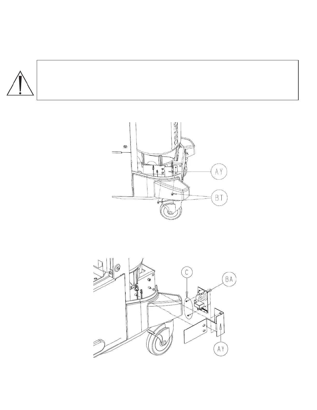
1. Using a 3/16” allen wrench, remove the two socket head cap screws (P/N 0004-645-
000) (BT) that hold the IR board bracket (P/N 0702-001-326) (AY) to the rover chassis.
2. Disconnect the two cables labeled power coupler PCBA going to the rover power
coupler PCBA (P/N 0702-001-806) (BA).
3. Using a 7/64” allen wrench, remove the two socket head cap screws (P/N 0004-529-
000) (C) that hold the rover power coupler PCBA (P/N 0702-001-806) (BA) to the IR
board bracket (P/N 0702-001-326) (AY).
4. Remove the circuit board and set aside.
2-67

 Loading...


