The input to the power distribution board is the control signal from the main
control board (in the UIP). Again, the technician will not be able to verify these inputs at
the backplane of this assembly. Instead we can proceed directly to the main control
board to verify the inputs from the membrane switch and the control signal output to the
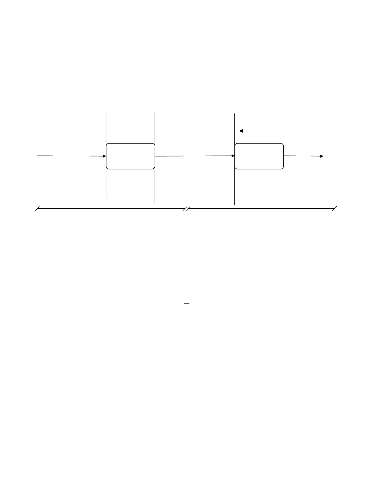
power distribution board. Figure 3 illustrates how the bracket moves again to
encompass the membrane switch input, main control board, and the control signal
output.
Main Control
Board
From Membrane
Switch
Control
From UIP
Input Device Output
Power Distribution
Board
12 vdc
Third Check : Verify control signal from main control board
2nd Check : Verify output from power distribution board
Previous Check
Figure 3: Verify Input From Membrane Switch
Thus far we have determined that the 12 volt output was not present at the IV
pole connector, and that the interface from the power control board to the IV pole is
intact. Since we can not check for 12vdc leaving the power distribution board, we have
no way of knowing if it is operating properly. For now, we will go further towards the
source of the signal to determine where the failure is occurring.
Keep in mind that the signal source is
the membrane switch. When the user
presses the IV pole up button, the motor turns on and the pole extends. Our next step is
to determine if the control signal is coming from the membrane switch. This is
accomplished by measuring the resistance at the ribbon cable between pins 1 and 6. If
the resistance starts open and ohms closed when the button is pressed, then the input
to the main control board is considered good. If the two points do not ohm check good,
then the membrane switch should be replaced.
Assuming the membrane switch is good, the only possible solutions that remain
are a faulty main control board, or the interface between the main control board and the
power distribution board. The most logical check at this point would be to ohm the wire
harness from the main control board to the power distribution board. This would verify
that the interface is intact. If the harness does not ohm correctly then it should be
repaired or replaced and the checks made again.
If the harness check ok, then there is only one step remaining before
troubleshooting is complete. A good input to both the main control board (the membrane
5-3
 Loading...


