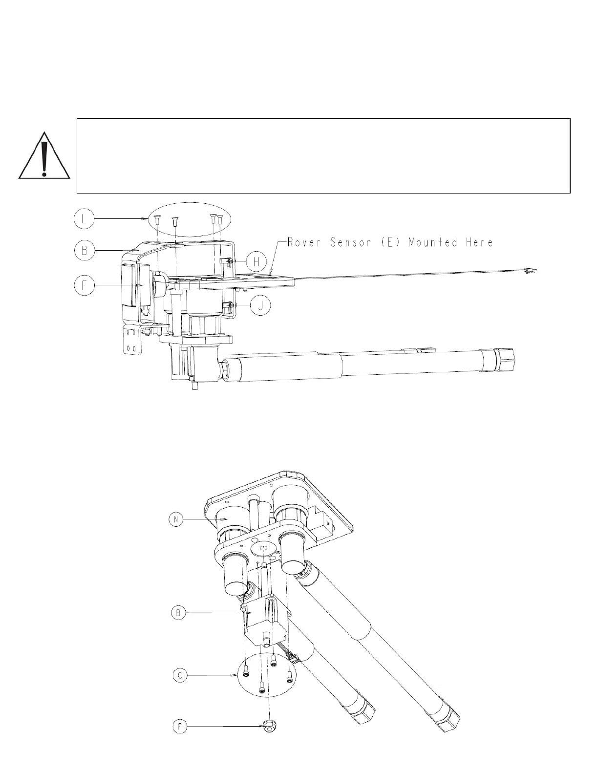
4. Using a 1/8” allen wrench remove four socket flat countersunk head cap screws (P/N
0004-346-000) (L) and separate the actuator strike plate (P/N 0702-014-111) (B) by
lifting it upwards.
Caution: the extended hall sensor (P/N 0702-014-119) (H), the rover hall sensor (P/N
0702-014-106) (E), the hall sensor (P/N 0702-014-906) (J), and the docker power coupler
assembly (P/N 0702-014-114) (F) are all mounted to the strike plate. Each component has
a wiring harness attached to it. Be careful not to get the connectors caught on anything
when the removing the actuator strike plate (P/N 0702-014-111) (B).
5. Using a ½” socket, unthread and remove the flange nut (P/N 0015-007-000) (F) on the
stepper motor (P/N 0702-014-123) (B). Remove four socket head cap screws (P/N
0004-526-000) (C) to separate the stepper motor (P/N 0702-014-123) (B) from the
coupling assembly (P/N 0702-014-120) (N).
4-11
 Loading...


