Caution: Ensure that both canisters are empty prior to removing them.
Removing the canisters with fluid inside will cause the fluid to leak into the
chassis area.
Caution: DO NOT lift the large canister assembly completely out of the
chassis once the hardware has been removed! On some models, the
connection behind the canister is inaccessible until after the canister hardware
is removed, and the canister rotated slightly. Proceed with caution!
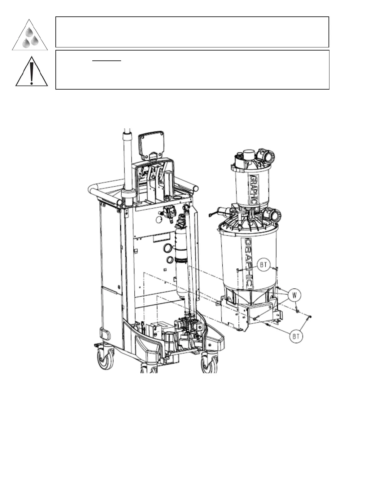
12. Remove the four socket head cap screws (P/N 0004-645-000) (BT) and four flat
washers (P/N 0011-507-000) (W) that hold the large canister assembly (P/N 702-1-
320) (AD) to the rover chassis. (Note that the small canister will still be attached.)
13. Unplug the connector labeled large can PCBA from the canister calibration PCBA
(P/N 702-1-803) (D). If the connector is behind the canister, slowly lift the large
canister assembly (P/N 702-1-320) (AD) up until the bottom bracket clears the
coupling block (P/N 702-1-600). Then rotate the large canister assembly (P/N 702-1-
320) (AD) clockwise approximately 10° and remove the connector.
14. Continue to remove the large canister assembly (P/N 702-1-320) (AD) out of the
chassis assembly and set aside.
2-30
 Loading...


