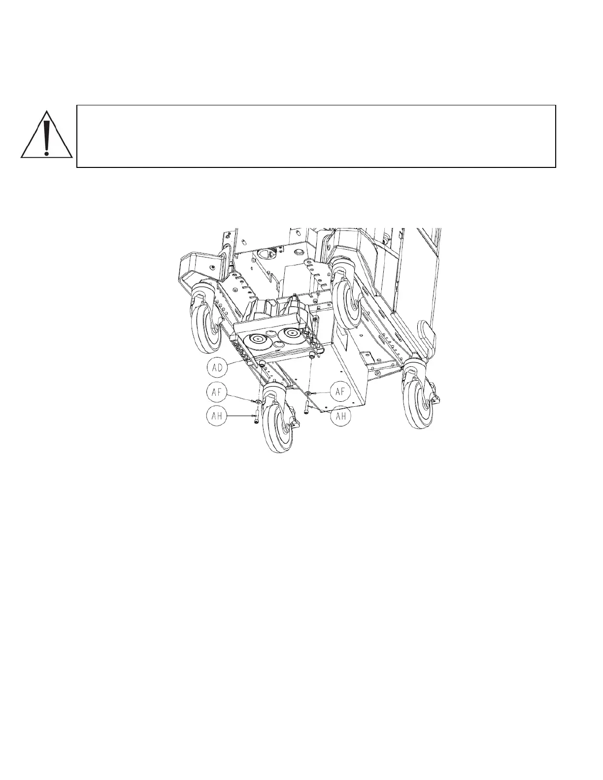
3. Once the four screws have been removed, remove the two coupling block rails (P/N
702-1-603) (AF) and set aside.
Note: Be aware of the orientation of the coupling block rails. There are guide pins to
keep the rail aligned, but it can be installed backwards as well as upside down. The
sloped portion of the rail should point away from the vacuum pump and towards the
floor.
4. Remove the remaining two socket head cap screws (P/N 0004-542-000) (AH) and two
¼” flat washers (P/N 0011-507-000) (AE) using a 3/16” allen wrench.
5. Remove the coupling block assembly (P/N 702-1-600) (AD) by forcing it downward
and set aside.
2-41
 Loading...


