OnAir 2000M2 Digital Mixing Console
Date printed: 12.11.03 SW V4.0 Configuration 3-1
3 CONFIGURATION
The console configuration is divided into hardware and software configu-
ration.
3.1 Software Configuration
The software configuration defines the functionality of the console. SW
configuration is described in chapter 12 of the OnAir 2000M2 Operating
Instructions manual.
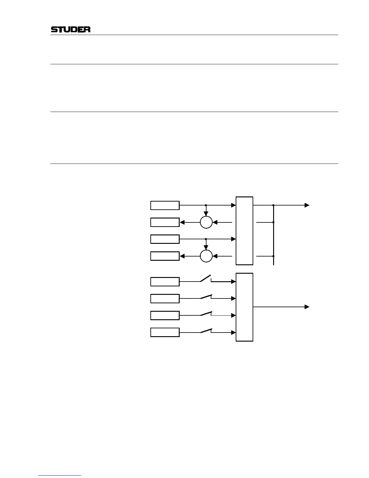
3.1.1 N–1 Configuration
Unlike in analog mixing consoles (where the N–1 signal is derived from
the output sum by subtracting a channel signal), the N–1 are separate buses
in the OnAir 2000M2.
N–1 in Analog Mixing Consoles:
N–1 in Digital Mixing Consoles:
The number of N–1 buses is limited by the maximum number of output
buses which can be handled by the signal processing. The OnAir 2000M2
has two N–1 buses (N–1A, N–1B), and four additional N–1C...F buses
available as an option. All of them are mono buses.
If a certain channel shall be routed to an N–1 bus, the corresponding field
in the input configuration page must be defined (refer to chapter 12.2.1 of
the OnAir 2000M2 Operating Instructions). Talkback to both N–1 buses is
possible from the control room and from the studio.
Channel 1
Channel 2
Channel 3
Channel n
(N–1) A
Σ
OFF
ON
ON
ON
Channel x
(N–1) x
Channel y
(N–1) y
Channel x
Σ
+
+
–
–