OnAir 2000M2 Digital Mixing Console
4-4 Alignment SW V4.0 Date printed: 12.11.03
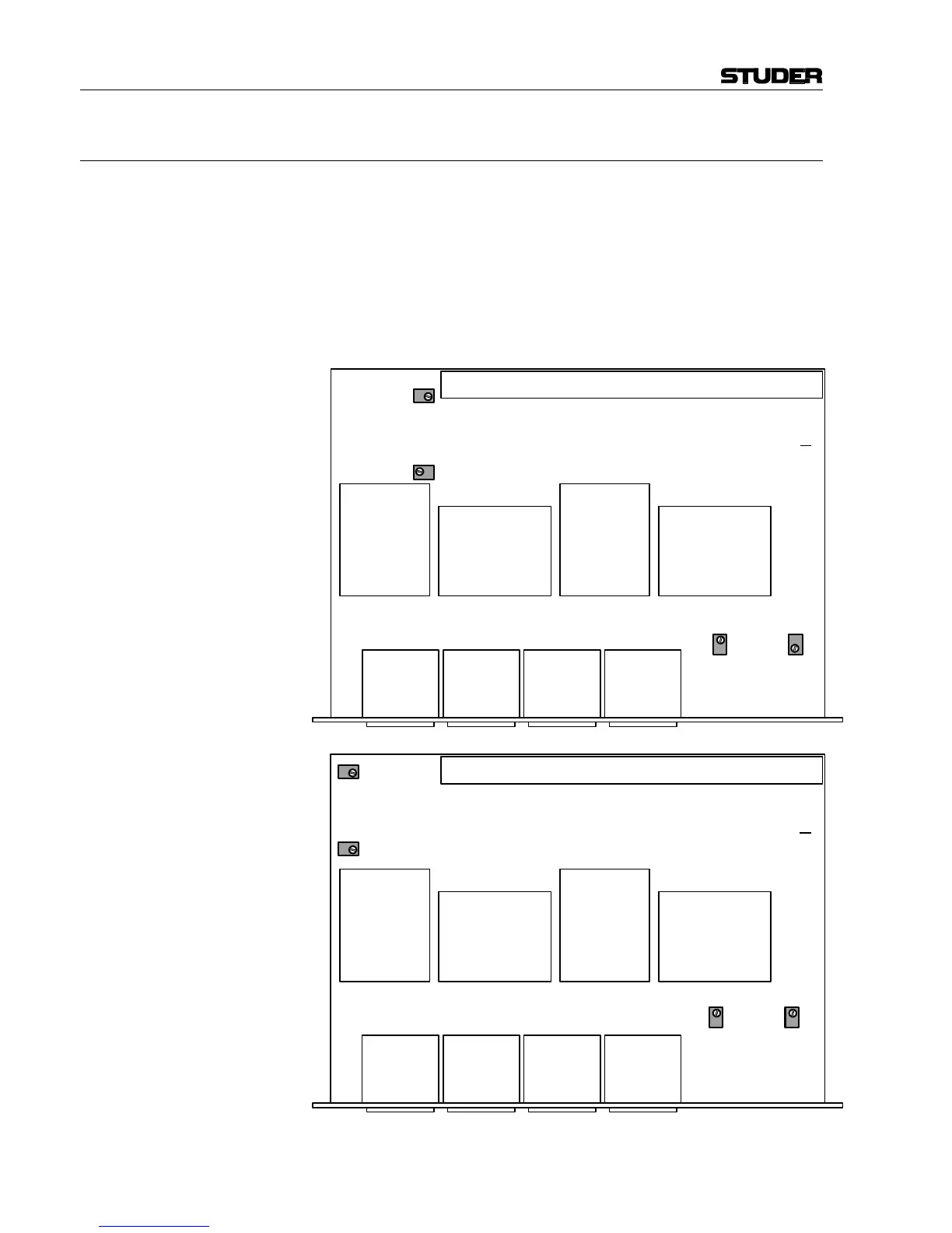
4.3.2 Dual Analog Output Module 1.942.121
Notes: Trimmer potentiometer locations are different for the two PCB versions
...81 and ...82, as indicated in the two drawings below.
• Feed a test signal with your particular nominal level (e.g. +6 dBu) to the
input of an analog or digital line input module.
• Set the fader of the corresponding channel to the 0 dB position.
• Route the signal to the output which is to be adjusted.
• Connect an AF voltmeter to this output.
• Adjust for a reading of your particular nominal level (e.g. +6 dBu) on the
AF voltmeter according to the drawings.
RA1
OUTPUT LEVEL
A LEFT
RA2
OUTPUT LEVEL
A RIGHT
RA3
OUTPUT LEVEL
B LEFT
RA4
OUTPUT LEVEL
B RIGHT
RA1
OUTPUT LEVEL
A RIGHT
RA2
OUTPUT LEVEL
A LEFT
RA3
OUTPUT LEVEL
B RIGHT
RA4
OUTPUT LEVEL
B LEFT
Dual Analog
Output Module
1.942.121. 81
Dual Analog
Output Module
1.942.121. 82